Widom
Smart Dry Contact Switch
SKU: WIDEWSD


Quickstart
This is a
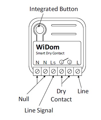
Pressing any sequence of click on the integrated button.
Important safety information
Please read this manual carefully. Failure to follow the recommendations in this manual may be dangerous or may violate the law. The manufacturer, importer, distributor and seller shall not be liable for any loss or damage resulting from failure to comply with the instructions in this manual or any other material. Use this equipment only for its intended purpose. Follow the disposal instructions. Do not dispose of electronic equipment or batteries in a fire or near open heat sources.Product Description
WiDom Smart Dry Contact Switch is very easy to install and works with both momentary and toggle switches.
It operates in any Z-Wave network with other Z-Wave/Z-Wave Plus certified devices and controllers from any other manufacturer. As a constantly powered node, WiDom Smart Double Switch will act as repeater regardless of the vendor in order to increase the reliability of the network.
Installation

Product Usage
| Reset to factory default | 6 consecutive clicks on the integrated button |
| Inclusion | Pressing any sequence of click on the integrated button. |
| Exclusion | Pressing any sequence of click on the integrated button. |
| NIF | XXXNIF |
| Wakeup | XXXWakeupDescription |
| Protection | XXXProtection |
| FirmwareUpdate | XXXFirmwareUpdate |
| SetAssociation | XXXSetAssociation |
Association Groups:
| Group Number | Maximum Nodes | Description |
|---|---|---|
| 1 | 8 | Lifeline |
| 2 | 8 | 1x Click - Basic Set |
| 3 | 8 | 2x Click - Basic Set |
| 4 | 8 | 3x Click - Basic Set |
Configuration Parameters
Parameter 1: Numbers of clicks on the external switch to control the load
Defines which sequences of clicks control the load. Size: 1 Byte, Default Value: 7
| Setting | Description |
|---|---|
| 0 | Disabled |
| 1 | One Click |
| 2 | Two Click |
| 4 | Three Click |
| 7 | All |
Parameter 4: Value used for devices belonging to Group 2 when the external switch receives 1 Click
Size: 1 Byte, Default Value: 100
| Setting | Description |
|---|---|
| 0 | Off |
| 1 - 99 | Dimming purpose |
| 100 | The same value of dry contact status |
| 255 | On |
Parameter 5: Value used for devices belonging to Group 3 when the external switch receives 2 Clicks
Size: 1 Byte, Default Value: 100
| Setting | Description |
|---|---|
| 0 | Off |
| 1 - 99 | Dimming purpose |
| 100 | The same value of dry contact status |
| 255 | On |
Parameter 6: alue used for devices belonging to Group 4 when external switch receives 3 Clicks
Size: 1 Byte, Default Value: 100
| Setting | Description |
|---|---|
| 0 | Off |
| 1 - 99 | Dimming purpose |
| 100 | The same value of dry contact status |
| 255 | On |
Parameter 10: Timer to switch OFF the Relay
Defines the time after which the relay is switched OFF. Size: 2 Byte, Default Value: 0
| Setting | Description |
|---|---|
| 0 | Timer disabled |
| 1 - 32000 | Number of time units (see parameter No.15) after which the dry contact is switched OFF |
Parameter 11: Timer to switch ON the Relay
Defines the time after which the relay is switched ON. Size: 2 Byte, Default Value: 0
| Setting | Description |
|---|---|
| 0 | Timer disabled |
| 1 - 32000 | Number of time units (see parameter No.15) after which the dry contact is switched ON |
Parameter 15: Timer scale
Defines the time unit used for parameters No.10 and No.11. Size: 2 Byte, Default Value: 1
| Setting | Description |
|---|---|
| 1 | Tenth of seconds |
| 2 | Seconds |
Parameter 20: One Click Scene Activation Set
Defines the Scene Activation Set value sent to the Lifeline group with 1 Click on the external switch. Size: 2 Byte, Default Value: 0
| Setting | Description |
|---|---|
| 0 | No value is sent |
| 1 - 255 | Value sent to the Lifeline group |
Parameter 21: Two Clicks Scene Activation Set
Defines the Scene Activation Set value sent to the Lifeline group with 2 Clicks on the external switch. Size: 2 Byte, Default Value: 0
| Setting | Description |
|---|---|
| 0 | No value is sent |
| 1 - 255 | Value sent to the Lifeline group |
Parameter 22: Three Clicks Scene Activation Set
Defines the Scene Activation Set value sent to the Lifeline group with 3 Clicks on the external switch. Size: 2 Byte, Default Value: 0
| Setting | Description |
|---|---|
| 0 | No value is sent |
| 1 - 255 | Value sent to the Lifeline group |
Parameter 60: Start-up Status
Defines the status of the device following a restart. Size: 1 Byte, Default Value: 3
| Setting | Description |
|---|---|
| 1 | Relay ON |
| 2 | Relay Off |
| 3 | Status prior to restart |
Parameter 62: Type of external switch
Defines the type of external switch connected to the device. Size: 1 Byte, Default Value: 1
| Setting | Description |
|---|---|
| 0 | The actions on the external switch are ignored. In this mode, the device can only be controlled through the network. |
| 1 | The external switch is a momentary switch type |
| 2 | The external switch is a traditional switch (toggle switch) |
Technical Data
| Dimensions | 37 x 37 x 17 mm |
| Weight | 27 gr |
| Hardware Platform | ZM5101 |
| EAN | 8059265060061 |
| IP Class | IP 20 |
| Voltage | 230 V |
| Load | 13 A |
| Device Type | Relais Switch |
| Generic Device Class | Binary Switch |
| Specific Device Class | Binary Power Switch |
| Firmware Version | 01.00 |
| Z-Wave Version | 06.04 |
| Z-Wave Product Id | 0x0149.0x1214.0x0900 |
| Frequency | Europe - 868,4 Mhz |
| Maximum transmission power | 5 mW |