Popp
Strike Lock Control
SKU: POPE012501


Quickstart
This is a
Important safety information
Please read this manual carefully. Failure to follow the recommendations in this manual may be dangerous or may violate the law. The manufacturer, importer, distributor and seller shall not be liable for any loss or damage resulting from failure to comply with the instructions in this manual or any other material. Use this equipment only for its intended purpose. Follow the disposal instructions. Do not dispose of electronic equipment or batteries in a fire or near open heat sources.What is Z-Wave?
Z-Wave is the international wireless protocol for communication in the Smart Home. This device is suited for use in the region mentioned in the Quickstart section.
Z-Wave ensures a reliable communication by reconfirming every message (two-way communication) and every mains powered node can act as a repeater for other nodes (meshed network) in case the receiver is not in direct wireless range of the transmitter.
This device and every other certified Z-Wave device can be used together with any other certified Z-Wave device regardless of brand and origin as long as both are suited for the same frequency range.
If a device supports secure communication it will communicate with other devices secure as long as this device provides the same or a higher level of security. Otherwise it will automatically turn into a lower level of security to maintain backward compatibility.
For more information about Z-Wave technology, devices, white papers etc. please refer to www.z-wave.info.
Product Description
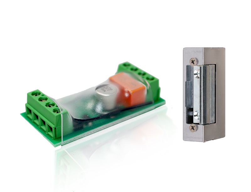
This electric Strike Lock control is a Security Enabled Z-Wave Plus Product. An Security Enabled Z-Wave Controller must be used to fully utilize this product. An electric strike is an access control device used to lock and release doors. Electric strikes are installed in or on the doorframe and work in conjunction with mechanical door lock, on the principle of electronically controlling the rotation of the keeper allowing for door opening without manual retraction of the mechanical door lock. This product combines a 16 mm thick strike lock (that will fit into almost all door formats) with a Z-Wave plus empowered wireless control. The lock mechanics and the Z-Wave control are operated by a 9V block battery or an external 8-12V AC / 8-24V DC transformer. The Z-Wave control accepts commands to open or close the strike. Depending on the configuration of the DoorLock CC, the door will be locked automatically after a certain time even if no ‘close? command was sent.
The device can be used standalone and within every conventional Intercom system controlling strike locks.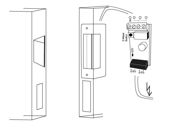
Prepare for Installation / Reset
Please read the user manual before installing the product.
In order to include (add) a Z-Wave device to a network it must be in factory default state. Please make sure to reset the device into factory default. You can do this by performing an Exclusion operation as described below in the manual. Every Z-Wave controller is able to perform this operation however it is recommended to use the primary controller of the previous network to make sure the very device is excluded properly from this network.
Reset to factory default
This device also allows to be reset without any involvement of a Z-Wave controller. This procedure should only be used when the primary controller is inoperable.
To do a factory reset press the Z-Wave button on the bottom of the device for at least 10 seconds.
Safety Warning for Batteries
The product contains batteries. Please remove the batteries when the device is not used. Do not mix batteries of different charging level or different brands.
Installation
The Strike-Lock has a IP 20 protection class, hence it is not recommended to install the device directly outdoors. Depending in its power situation the device will either act as Z-Wave repeater or as so-called FLiRS-device (frequently listening battery operated). Any voltage > 12 V DC is detected as mains powered; any voltage <= 9 V is detected as battery operated using the 9 V battery block.
There are four possible scenarios you want to install the Strike-Lock. It is highly recommended to test the electrial wiring and setup prior to making any change on the mechanical door.
No existing installation of an electrical door opener and no AC power on the spot
In this case you will have to mechanically install the strike lock of your choice, find a place for the battery and the strike lock control nearby and implement the wiring as shown below: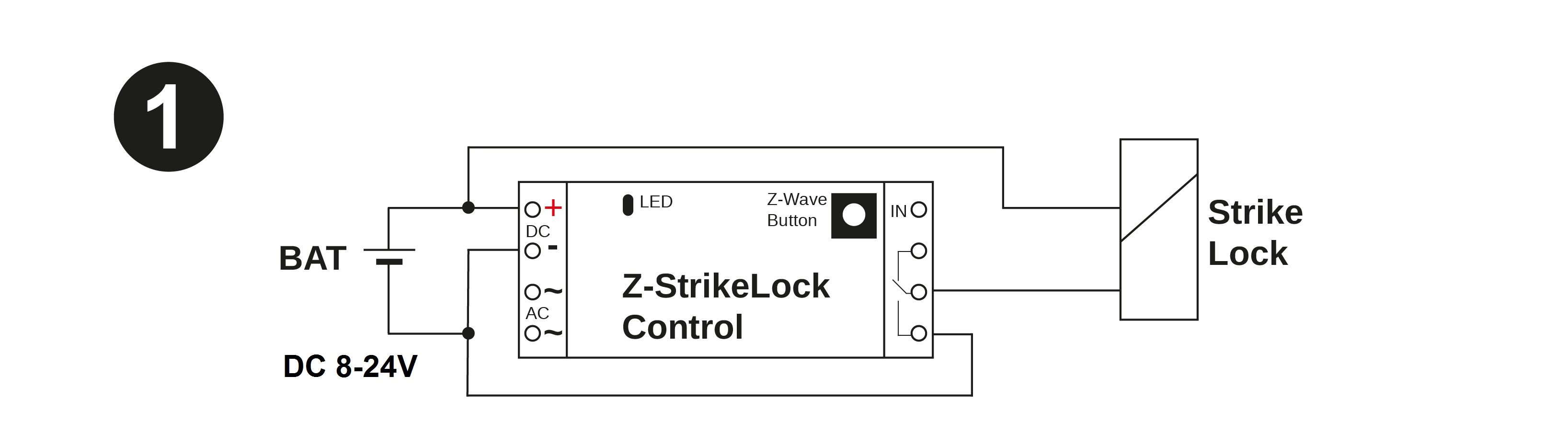
No existing installation of an electrical door opener but dedicated AC Power on the spot
You may find AC power on the spot if the door is near a traditional door bell button that is powered by a conventional transformer. In this case you will have to install the mechanican strike look and find a dry place for the strike lock control. The distance between the transformer and the strike lock control and between the strike lock control and the strike depends on the qulity of the transformer and the quality of the wires used. You may orientate on the distances between the existing door bell button and the transformer (usually placed inside the mains distibution panel).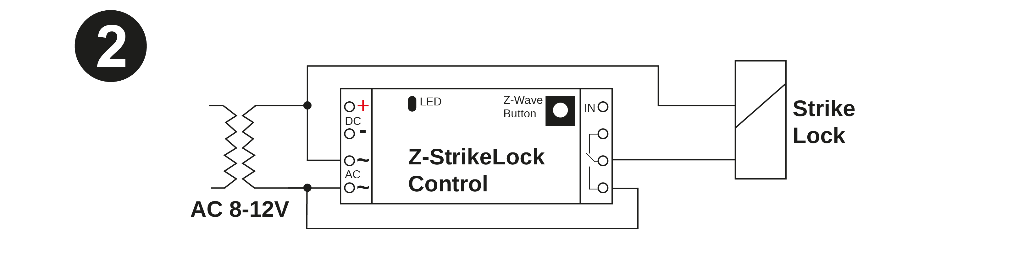
Existing traditional analog door bell installation
Existing door bell installations usually connect the door bell button and the bell using two wire cables to the mains distribution panel where the AC transformer is placed. The image below shows how to change this existng cabling to power the strike lock in parallel.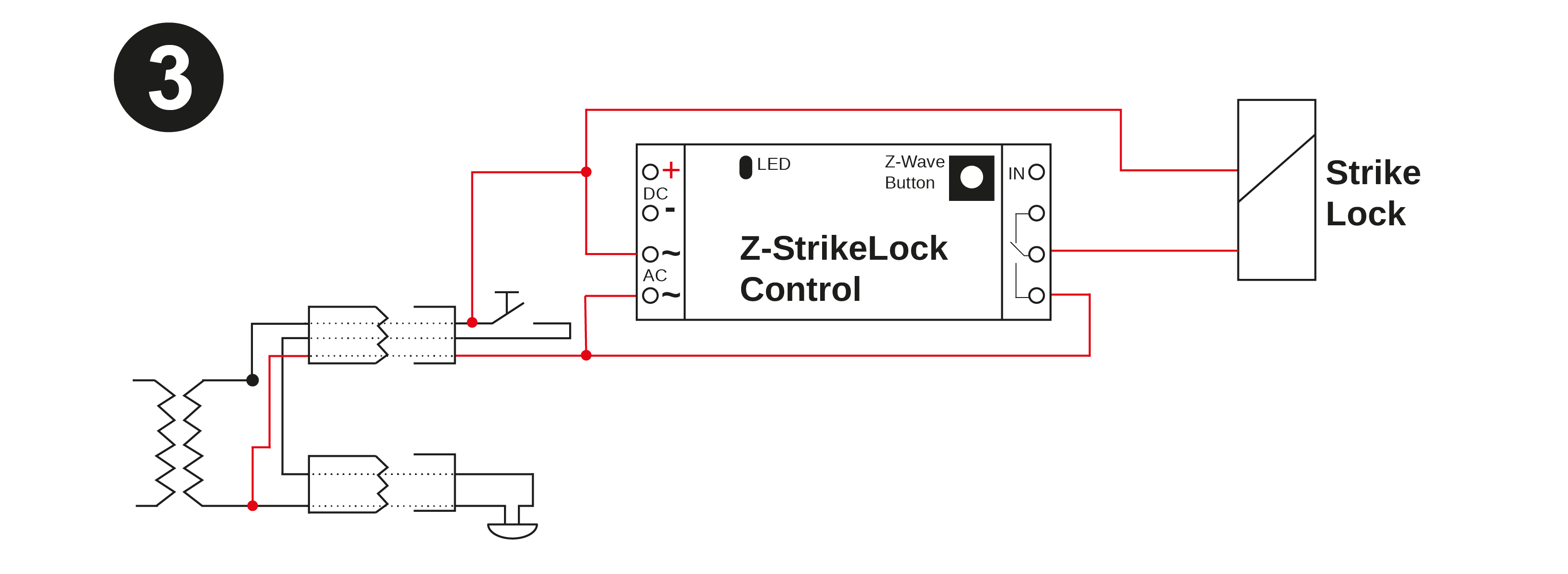
Existing (multi user) Intercom system with integrated door opener
Most multi-floor appartment houses are equipped with an audio communication between the main door and the appartments to identify visitors. Such a system usually contains a way to open the mains door using a button on the Intercom system. Communication between the different terminals inside the appartments and a central control are of proprietary nature. The strike lock is then controlled from the central controller device using two dedicated wires.
The Popp Strike lock can be used in such an installation independend of the type of the Intercom solution and without interfering the existing Intercom infrastructure. The image below shows the required wiring. The system will with both battery operation and AC power supply (image shows battery solution only).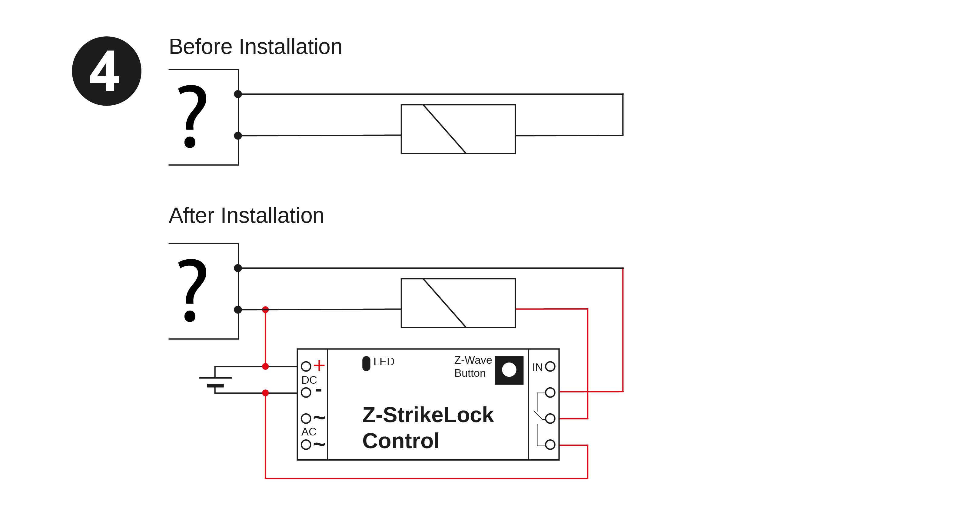
Mechanical Installation of the Strike Lock (if needed)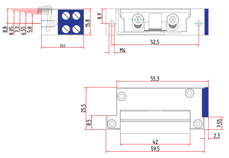
- Remove the existing door plate by unscrewing it with your screwdriver. Be careful not to strip the screws as this will make removal much more difficult. Now you have two options. Either you find a plate that already has the cut-outs to fit the strike lock or you have to cut your existing plate to accommodate the strike lock. The strike lock is connected to the door strike using two screws in a distance of 55 cm. This is a standardized distance and the two holes should already be available on almost all plates in the market. If they are not available you have to drill two holes of diameter of 4 mm in equal distance from the cut out that accommodates the door latch. The cut-out can be done using a simple metal saw or a Dremel.
- The next step is to make sure there is enough room behind the plate so that the look fits in. Our strike look is particularly small so the required space allocation is only 16,6 mm width and 26 mm deep.
- Now you will need to decide where to place the control electronics. You can place it near the strike using short wires or place is next to your power supply using longer wires.
Dry Input Handling
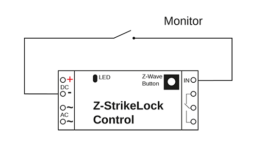
The strike lock control has one dry input terminal marked as "IN". This can be used to indicate if a door is opened or closed by connecting it to DC ground utilizing a simple external switch. Some third party strike locks offer so-called monitoring contact exactly delivering this function. Having a monitor contact on a strike lock or any other mechanical contact will save the need for an additional wireless door contact to monitor the status of the door. Whenever the door is open the strike magnet is not powered anymore to save energy. The strike magnet is also unpowered immediately when an opening door is detected. Events from the dry inout can control other Z-Wave devices using BASIC command class and association group 2. The configuation parameters 1 and 2 define the BASIC commands used.
Inclusion/Exclusion
On factory default the device does not belong to any Z-Wave network. The device needs to be added to an existing wireless network to communicate with the devices of this network. This process is called Inclusion.
Devices can also be removed from a network. This process is called Exclusion. Both processes are initiated by the primary controller of the Z-Wave network. This controller is turned into exclusion respective inclusion mode. Inclusion and Exclusion is then performed doing a special manual action right on the device.
Inclusion
Exclusion
Product Usage
The strike lock control allows opening doors using a strike lock. It is recommended to use the device together with a Z-Wave door sensor indicating the status of the door resp. using an external dry contact to serve the same purpose. According to Z-Wave policies the wireless control of the door lock is allowed with secure Door Lock commands only.
The Popp Hub central controller offers a App from the App store that combines both functions into one element showing the three states of a door (open, close and locked, close but unlocked) and allows ot control the strike lock. Of course any other third party software or central Z-Wave controller can operate the door lock as well.
Some estimation on battery life
The strike lock control itself only needs about 50 yA of power. An 9 V lithium battery block will last more than 4 years. The operation of a strike lock however costs energy. Just assume 5 (5 second long) operations per day will drain the battery in about one year.
Notifications
The device will send the following notifications to the central controller:
- Battery Status (Battery Command Class Report)
- External Dry Contact on/off (Notification Type 0x06 with events open=0x16 and closed=0x17)
- Door Lock Open/Close (Door Lock Command Class Report)
- Local Device Reset (Device Reset Locally Command Class Report)
Node Information Frame
The Node Information Frame (NIF) is the business card of a Z-Wave device. It contains information about the device type and the technical capabilities. The inclusion and exclusion of the device is confirmed by sending out a Node Information Frame. Beside this it may be needed for certain network operations to send out a Node Information Frame. To issue a NIF execute the following action: A single click on the button will issue a NIF. The type of the NIF depends on the powering situation. In cas the device detects to me mains operated the NIF is inform the controller that this device is routing and always wirelessly active. In case battery operation is detected the NIF will contain this information (its a FliRS).
Quick trouble shooting
Here are a few hints for network installation if things dont work as expected.
- Make sure a device is in factory reset state before including. In doubt exclude before include.
- If inclusion still fails, check if both devices use the same frequency.
- Remove all dead devices from associations. Otherwise you will see severe delays.
- Never use sleeping battery devices without a central controller.
- Dont poll FLIRS devices.
- Make sure to have enough mains powered device to benefit from the meshing
Firmware-Update over the Air
This device is capable of receiving a new firmware 'over the air'. The update function needs to be supported by the central controller. Once the controller starts the update process, perform the following action to confirm the firmware update: Once the firmware update process has started double click the Z-Wave button to confirm firmware update process.
Association - one device controls an other device
Z-Wave devices control other Z-Wave devices. The relationship between one device controlling another device is called association. In order to control a different device, the controlling device needs to maintain a list of devices that will receive controlling commands. These lists are called association groups and they are always related to certain events (e.g. button pressed, sensor triggers, ...). In case the event happens all devices stored in the respective association group will receive the same wireless command wireless command, typically a 'Basic Set' Command.
Association Groups:
| Group Number | Maximum Nodes | Description |
|---|---|---|
| 1 | 10 | Lifeline |
| 2 | 10 | External Dry Contact |
Configuration Parameters
Z-Wave products are supposed to work out of the box after inclusion, however certain configuration can adapt the function better to user needs or unlock further enhanced features.
IMPORTANT: Controllers may only allow configuring signed values. In order to set values in the range 128 ... 255 the value sent in the application shall be the desired value minus 256. For example: To set a parameter to 200 it may be needed to set a value of 200 minus 256 = minus 56. In case of a two byte value the same logic applies: Values greater than 32768 may needed to be given as negative values too.
Parameter 1: Value of OPEN-Command
This parameter defines the value of the BASIC Set command issued into association group 2 when the dry contact opens. Size: 1 Byte, Default Value: 0
| Setting | Description |
|---|---|
| 0 - 99 | Command Value |
Parameter 2: Value of CLOSE-command
This parameter defines the value of the BASIC Set command issued into association group 2 when the dry contact closes. Size: 1 Byte, Default Value: 99
| Setting | Description |
|---|---|
| 0 - 99 | Command Value |
Parameter 5: Force FliRS Mode
Size: 1 Byte, Default Value: 0
| Setting | Description |
|---|---|
| 0 | Depends on Power Status in Inclusion Moment |
| 1 | Force FLiRS Mode |
Technical Data
| Dimensions | 56x25x14 mm |
| Weight | 20.31 gr |
| Hardware Platform | ZM5202 |
| EAN | 0019962012501 |
| IP Class | IP 20 |
| Voltage | 8-12V AC / 8-24V DC |
| Battery Type | 1 * 9V Block |
| Device Type | Door Lock |
| Network Operation | Listening Slave |
| Firmware Version | 1.5 |
| Z-Wave Version | SDK 6.51.09 |
| Certification ID | ZC10-17035482 |
| Z-Wave Product Id | 0x0154.0x0005.0x0001 |
| Frequency | Europe - 868,4 Mhz |
| Maximum transmission power | 5 mW |
Supported Command Classes
- Association Grp Info
- Device Reset Locally
- Zwaveplus Info
- Door Lock
- Configuration
- Alarm
- Manufacturer Specific
- Powerlevel
- Firmware Update Md
- Battery
- Association
- Version
- Security
Controlled Command Classes
- Basic
Explanation of Z-Wave specific terms
- Controller — is a Z-Wave device with capabilities to manage the network. Controllers are typically Gateways,Remote Controls or battery operated wall controllers.
- Slave — is a Z-Wave device without capabilities to manage the network. Slaves can be sensors, actuators and even remote controls.
- Primary Controller — is the central organizer of the network. It must be a controller. There can be only one primary controller in a Z-Wave network.
- Inclusion — is the process of adding new Z-Wave devices into a network.
- Exclusion — is the process of removing Z-Wave devices from the network.
- Association — is a control relationship between a controlling device and a controlled device.
- Wakeup Notification — is a special wireless message issued by a Z-Wave device to announces that is able to communicate.
- Node Information Frame — is a special wireless message issued by a Z-Wave device to announce its capabilities and functions.