MCO Home
Touch Panel Dimmer UK
SKU: MCOEDT311

Quickstart
This is a
Important safety information
Please read this manual carefully. Failure to follow the recommendations in this manual may be dangerous or may violate the law. The manufacturer, importer, distributor and seller shall not be liable for any loss or damage resulting from failure to comply with the instructions in this manual or any other material. Use this equipment only for its intended purpose. Follow the disposal instructions. Do not dispose of electronic equipment or batteries in a fire or near open heat sources.Product Description
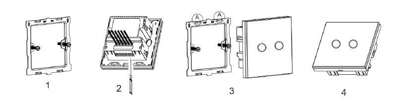
Installation

Product Usage
1. Touch “+” 4 times and its green LED flashes, then touch “-” 4 times and 2 green LED flashes for 3 sec. The panel enters Dimming mode setting.
2. During setting, the “+” LED color will inform the current dimming mode:
|
Leading edge for inductive loads
|
Trailing edge for capacitive or resistive loads
|
On/off only
|
Automatically detection
|
|---|---|---|---|
|
Orange LED flashing
|
Green LED flashing
|
Orange and Green LEDs flashing together
|
Orange and Green LEDs flashing alternately
|
4. Touch “+” to confirm the mode you chose, the mode’s LED color will flash 3 sec to finish the setting. If Auto detection chosen, pls wait the panel to detect the light source and confirm leading
| Reset to factory default | Press 10 times of any button or exclude the device from Z-Wave network, then cut off the main power. The factory setting will be restored. |
| Inclusion | 1. Set controller into Add mode and press 3 clicks on "+" or "-" button to add. If succeed, green LED flicks 4 times.
2. If an external switch panel wired, press/toggle the button on that panel 3 times also can add the network (To make the external panel work, set the parameter 14 with value 1, 2, 3 or 4). |
| Exclusion | 1. Set controller into Remove mode, and press 3 clicks on "+" or "-" button to remove. If succeed, green LED flicks 4 times.
2. If an external switch panel wired, press/toggle the button on that panel 3 times also can remove the network (To make the external panel work, set the parameter 14 with value 1, 2, 3 or 4). |
| NIF | XXXNIF |
| Wakeup | XXXWakeupDescription |
| Protection | XXXProtection |
| FirmwareUpdate | XXXFirmwareUpdate |
| SetAssociation | XXXSetAssociation |
Association Groups:
| Group Number | Maximum Nodes | Description |
|---|---|---|
| 1 | 1 | Lifeline - Send unsolicited reports to the gateway |
| 2 | 5 | Send Switch_Multilevel CC to associated devices |
| 5 | 5 | Associate with Key “+” Send Basic Set CC to associated devices |
| 8 | 5 | Associate with Key “-” Send Basic Set CC to associated devices |
Configuration Parameters
Parameter 1: Dimmer state saved or not when power down
Size: 1 Byte, Default Value: 0
| Setting | Description |
|---|---|
| 0 | not saved,Dimmer will be off when powered again |
| 1 | saved,Dimmer will keep the same state when powered again |
Parameter 2: Dimming mode
Size: 1 Byte, Default Value: 1
| Setting | Description |
|---|---|
| 0 | leading edge |
| 1 | trailing edge |
| 2 | On/off only |
Parameter 3: Auto detection of dimming mode when powered on
Size: 1 Byte, Default Value: 0
| Setting | Description |
|---|---|
| 0 | Auto detection disabled |
| 1 | Auto detection enabled |
Parameter 4: LED Backlit brightness level
Size: 1 Byte, Default Value: 10
| Setting | Description |
|---|---|
| 0 | LED disabled |
| 1 - 10 | Min level - Max level |
Parameter 5: Minimum brightness level
The max level should always higher than min level Size: 1 Byte, Default Value: 1
| Setting | Description |
|---|---|
| 1 - 98 | percentage brightness level |
Parameter 6: Maximum brightness level
The max level should always higher than min level Size: 1 Byte, Default Value: 99
| Setting | Description |
|---|---|
| 2 - 99 | percentage brightness level |
Parameter 7: Single dimming step time(Manual)
Manual control realized by holding external button Size: 2 Byte, Default Value: 3
| Setting | Description |
|---|---|
| 1 - 2550 | Max 2.55s, in 10ms steps |
Parameter 8: Single dimming step size(Manual)
Manual control realized by holding external button Size: 1 Byte, Default Value: 1
| Setting | Description |
|---|---|
| 1 - 99 | percentage value (modification isn’t recommended) |
Parameter 9: Single dimming step time (Auto)
Auto control realized by: - one click; - double click of external button; - send Z-Wave CC Size: 2 Byte, Default Value: 3
| Setting | Description |
|---|---|
| 1 - 2550 | Max 2.55s, in 10ms steps |
Parameter 10: Single dimming step size (Auto)
Auto control realized by: - one click; - double click of external button; - send Z-Wave CC Size: 1 Byte, Default Value: 1
| Setting | Description |
|---|---|
| 1 - 99 | percentage value (modification isn’t recommended) |
Parameter 11: The dimming percentage when single touch of button “+” or “-”
With this parameter you can set the light level the lamp will reach when you turn on the lamp of single touch “+” Size: 1 Byte, Default Value: 0
| Setting | Description |
|---|---|
| 0 | the percentage get by the last button-holding touch |
| 1 - 99 | percentage value |
Parameter 12: Reporting interval for dimming level
Size: 1 Byte, Default Value: 10
| Setting | Description |
|---|---|
| 0 | No report during dimming |
| 1 - 255 | send report in1-255*10ms interval |
Parameter 13: External switch type
Size: 1 Byte, Default Value: 0
| Setting | Description |
|---|---|
| 0 | Button (Momentary buttons ) |
| 1 | Toggle (2-state Switches ) |
Parameter 14: External switch input
Size: 2 Byte, Default Value: 0
| Setting | Description |
|---|---|
| 0 | function disabled |
| 1 | wire 1 ex.switch key to S1 only |
| 2 | wire 1 ex.switch key to S2 only |
| 3 | wire 2 ex.switch keys to S1 and S2,each key can control both dimming directions |
| 4 | wire 2 ex.switch keys to S1 and S2, each key control one dimming direction |
Parameter 15: Energy meter reporting
Size: 1 Byte, Default Value: 0
| Setting | Description |
|---|---|
| 1 | Watt |
| 2 | KWH |
| 4 | Ampere |
| 8 | Voltage |
| 15 | All |
Parameter 16: Energy meter reporting interval
Size: Byte, Default Value: 16
| Setting | Description |
|---|---|
| 1 - 255 | n*1sec |
Parameter 17: Beep
Size: 1 Byte, Default Value: 1
| Setting | Description |
|---|---|
| 0 | beep disabled |
| 1 | beep enabled |
Parameter 32: Ampere alarm threshold
Size: 2 Byte, Default Value: 0
| Setting | Description |
|---|---|
| 0 | alarm disabled |
| 1 - 5000 | 1-5000*0.01 A alarm enabled |
Parameter 33: Voltage alarm threshold
Size: 2 Byte, Default Value: 0
| Setting | Description |
|---|---|
| 0 | alarm disabled |
| 1 - 10000 | 1-10000*0.1 V alarm enabled |
Parameter 255: Factory setting
Size: 1 Byte, Default Value: 0
| Setting | Description |
|---|---|
| 85 | FF Factory setting |
Technical Data
| Dimensions | 0.0860000x0.0860000x0.0420000 mm |
| Weight | 156 gr |
| Hardware Platform | ZM5202 |
| EAN | 6928954212000 |
| IP Class | IP 20 |
| Voltage | 230 V |
| Load | 20 - 200W |
| Device Type | Dimmer |
| Generic Device Class | Multilevel Switch |
| Specific Device Class | Routing Multilevel Switch |
| Firmware Version | 02.06 |
| Z-Wave Version | 04.3e |
| Z-Wave Product Id | 0x015f.0xd311.0x5102 |
| Frequency | Europe - 868,4 Mhz |
| Maximum transmission power | 5 mW |