Heatit (Thermo-Floor)
Heatit Z-TRM2fx
SKU: HEAE5430556


Quickstart
This is a
Important safety information
Please read this manual carefully. Failure to follow the recommendations in this manual may be dangerous or may violate the law. The manufacturer, importer, distributor and seller shall not be liable for any loss or damage resulting from failure to comply with the instructions in this manual or any other material. Use this equipment only for its intended purpose. Follow the disposal instructions. Do not dispose of electronic equipment or batteries in a fire or near open heat sources.Product Description
Heatit Z-TRM2fx is equipped with a single pole switch and it fits most System 55 frames (Elko RS16, Schneider Exxact, Gira, Jung etc.). The thermostat can withstand a load of max 13A /2900W at 230V. At higher loads the thermostat must control a contactor. The thermostat may be connected to two wired external sensors. The thermostat has the capacity of up to 8 associations (relays, wall plugs etc.).The thermostat is designed for electrical heating.
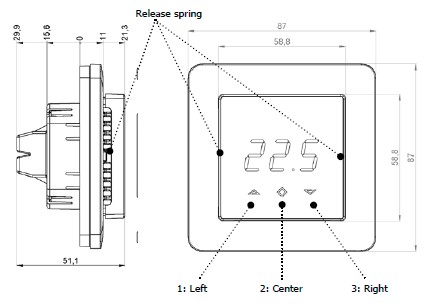
Installation
Product Usage
Now you are in programming mode. To scroll up and down in the menu use button 1 and 3 (left and right) to navigate.
OFF Turns the thermostat off.
Sensors:
SEn Select the right Ohm value for your external/floor sensor. NTC type (10, 12, 15, 22, 33 or 47kΩ). Default 10kΩ.
TEMPERATURE SHOWN IN DISPLAY
ALo Min Air/room temperature
The ECO-mode can also be activated by the pilot wire if this is connected. Example: 18°C. Some gateways also support switching between CO/ECO mode. In most circumstances, the CO/ECO function can be regarded as a home/away function.
| Reset to factory default | By pressing buttons Right and Center (down and confirm) for 20 seconds, the thermostat will perform a complete factory reset. |
| Inclusion | Press Center (confirm) for 10 seconds. The display will show OFF. Press Right (down) 4 times till you see Con in the display. Start adding mode by pressing Center (confirm) button for approximately 2 seconds. |
| Exclusion | Press Center (confirm) for 10 seconds. The display will show OFF. Press Right (down) 4 times till you see Con in the display. Start removing mode by pressing Center (confirm) button for approximately 2 seconds. |
| NIF | XXXNIF |
| Wakeup | XXXWakeupDescription |
| Protection | XXXProtection |
| FirmwareUpdate | XXXFirmwareUpdate |
| SetAssociation | XXXSetAssociation |
Association Groups:
| Group Number | Maximum Nodes | Description |
|---|---|---|
| 1 | 1 | Lifeline. (Normally used by the Z-Wave Controller) Sends: - Thermostat Setpoint Reports - Thermostat Mode Reports |
| 2 | 5 | Send Multilevel Sensor Reports. |
| 3 | 5 | Send Multilevel Sensor Reports. |
| 4 | 5 | Send Binary Switch Set commands representing the status of the internal relay. |
Configuration Parameters
Parameter 1: Operation Mode
Size: 1 Byte, Default Value: 0
| Setting | Description |
|---|---|
| 0 | Off |
| 1 | Heating mode |
| 2 | Cooling mode (not implemented) |
| 11 | Energy saving heating mode |
Parameter 2: Sensor mode
Size: 1 Byte, Default Value: 0
| Setting | Description |
|---|---|
| 0 | F-mode, floor sensor mode. |
| 3 | A2-mode, external room sensor mode |
| 4 | A2F-mode, external sensor with floor limitation |
Parameter 3: Floor sensor type
Size: 1 Byte, Default Value: 0
| Setting | Description |
|---|---|
| 0 | 10K NTC. |
| 1 | 12K NTC |
| 2 | 15K NTC |
| 3 | 22K NTC |
| 4 | 33K NTC |
| 5 | 47K NTC |
Parameter 4: Temperature control hysteresis (DIFF I)
Size: 1 Byte, Default Value: 5
| Setting | Description |
|---|---|
| 3 - 30 | 0.3°C - 3.0°C |
Parameter 5: Floor minimum temperature limit (FLo)
Size: 2 Byte, Default Value: 50
| Setting | Description |
|---|---|
| 50 - 400 | 5.0°C - 40.0°C |
Parameter 6: Floor maximum temperature limit (FHi)
Size: 2 Byte, Default Value: 400
| Setting | Description |
|---|---|
| 50 - 400 | 5.0°C - 40.0°C |
Parameter 7: Air (A2) minimum temperature limit (ALo)
Size: 2 Byte, Default Value: 50
| Setting | Description |
|---|---|
| 50 - 400 | 5.0°C - 40.0°C |
Parameter 8: Air (A2) maximum temperature limit (AHi)
Size: 2 Byte, Default Value: 400
| Setting | Description |
|---|---|
| 50 - 400 | 5.0°C - 40.0°C |
Parameter 9: Heating mode setpoint (CO)
Size: 2 Byte, Default Value: 210
| Setting | Description |
|---|---|
| 3 - 30 | 0.3°C - 3.0C |
| 50 - 400 | 5.0°C - 40.0°C |
Parameter 10: Energy saving mode setpoint (ECO)
Size: 2 Byte, Default Value: 180
| Setting | Description |
|---|---|
| 50 - 400 | 5.0°C - 40.0°C. |
Parameter 11: Cooling setpoint (COOL)
Size: 2 Byte, Default Value: 210
| Setting | Description |
|---|---|
| 50 - 400 | 5.0°C - 40.0°C |
Parameter 12: Floor sensor calibration
Size: 1 Byte, Default Value: 0
| Setting | Description |
|---|---|
| 0 - 40 | 0 - 4.0°C. |
| 215 - 255 | -4,0 - -0,1°C |
Parameter 13: External sensor calibration
Size: 1 Byte, Default Value: 0
| Setting | Description |
|---|---|
| 0 - 40 | 0 - 4.0°C. |
| 215 - 255 | -4,0 - -0,1°C |
Parameter 14: Temperature display
Selects which temperature is shown on the display. Size: 1 Byte, Default Value: 0
| Setting | Description |
|---|---|
| 0 | Display setpoint temperature |
| 1 | Display measured temperature |
Parameter 15: Button brightnessdimmed state
Configure the brightness of the buttons, in dimmed state. Size: 1 Byte, Default Value: 50
| Setting | Description |
|---|---|
| 0 - 100 | in % |
Parameter 16: Button brightnessactive state
Configure the brightness of the buttons, in active state. Size: 1 Byte, Default Value: 100
| Setting | Description |
|---|---|
| 0 - 100 | in % |
Parameter 17: Display brightnessdimmed state
Configure the brightness of the display, in dimmed state. Size: 1 Byte, Default Value: 50
| Setting | Description |
|---|---|
| 0 - 100 | in % |
Parameter 18: Display brightnessactive state
Configure the brightness of the display, in active state. Size: 1 Byte, Default Value: 100
| Setting | Description |
|---|---|
| 0 - 100 | in % |
Parameter 19: Temperature report interval
Time interval between consecutive temperature reports. Temperature reports can be also sent as a result of polling. Size: 2 Byte, Default Value: 60
| Setting | Description |
|---|---|
| 0 | Reporting of temperatures disabled |
| 30 - 32767 | in seconds |
Parameter 20: Temperature report hysteresis
The temperature report will be sent if there is a difference in temperature value from the previous value reported, defined in this parameter (hysteresis). Temperature reports can be also sent as a result of polling. Size: 1 Byte, Default Value: 10
| Setting | Description |
|---|---|
| 1 - 100 | 0.1°C - 10.0°C |
Parameter 21: Meter report interval
Time interval between consecutive meter reports. Meter reports can be also sent as a result of polling. Size: 2 Byte, Default Value: 60
| Setting | Description |
|---|---|
| 0 | Reporting of metering values is disabled |
| 30 - 32767 | in seconds |
Parameter 22: Meter report delta value
Delta value in kWh between consecutive meter reports. Meter reports can be also sent as a result of polling. Size: 1 Byte, Default Value: 10
| Setting | Description |
|---|---|
| 0 - 127 | A delta value of 0 - 12.7 kWh will result in a metering report. |
Technical Data
| Dimensions | 86,5 x 51,75 x 86,5 mm |
| Hardware Platform | ZM5101 |
| EAN | 7071236013495 |
| IP Class | IP IP 20 |
| Voltage | 230 V |
| Load | 13 A |
| Device Type | Thermostat - HVAC |
| Network Operation | Always On Slave |
| Firmware Version | HW: 2 FW: 3.03:03.02 |
| Z-Wave Version | 6.71.03 |
| Certification ID | ZC10-18116305 |
| Z-Wave Product Id | 0x019B.0x0003.0x0202 |
| IP (Ingress Protection) Rated | ok |
| Neutral Wire Required | ok |
| Sensors | HeatTarget TemperatureVoltageWater Temperature |
| Color | White |
| Thermostat Modes | AutoAwayCoolEnergy Save HeatHeat |
| Supported Meter Type | Electric Energy |
| Thermostat HVAC Systems Supported | Cool OnlyHeat OnlySimple Relay |
| Thermostat Power Source | Mains powered (120V/240V) |
| Firmware Updatable | Updatable by Consumer by RF |
| Supported Notification Types | Heat Alarm |
| Frequency | XXfrequency |
| Maximum transmission power | XXantenna |