Fibaro Group
Blind Control Insert 2
SKU: FIB_FGRM-222

Quickstart
This is a
To include the device into the network, turn the controller into the inclusion mode and then triple click the B-button or a push button connected to the S1 terminal. Further you can use the auto-inclusion mode by setting the controller into the inclusion mode and then connect voltage supply.
Important safety information
Please read this manual carefully. Failure to follow the recommendations in this manual may be dangerous or may violate the law. The manufacturer, importer, distributor and seller shall not be liable for any loss or damage resulting from failure to comply with the instructions in this manual or any other material. Use this equipment only for its intended purpose. Follow the disposal instructions. Do not dispose of electronic equipment or batteries in a fire or near open heat sources.Product Description
The Fibar Insert Motor Control FGRM-222 allows controlling motors for jalousies, blinds or other single-phase AC devices both wirelessly via Z-Wave and locally utilizing a traditional wall switch. Additionally to the Fibaro Blind Control Insert 1 (FGR-221) this device allows the control of garage doors and measuring the current and power consumption for the controlled devices and itself. This insert enables a precise positioning of motors with mechanical and electrical limit switch. In addition, this device has a power monitoring.
The device is placed in a wall box right behind the normal switch. The switch is not longer directly connected to the load but acts as input device for the Fibar insert that is controlling the load. The solution works with all switch design with or without neutral position as long as there is enough space in the wall box behind the switch. The device is just 15 mm height. The available space depends on the size of the traditional switch, the dimensions of the wall box and the amount of additional cabling placed in this box. This device is designed for a 3 wire system and needs a neutral wire in the wall box.
Installation
The motor control insert is designed to fit into standard circular European wall boxes with 60 mm diameter. With its 15 mm height, it can be also mounted behind traditional wall switches. This wall switch serves as an external control switch to controll loads. The relays are realized in the insert.
The inserts contacts N and L are connected directly with the mains distribution of the power network. The three wires of the motor are connected like shown in the figure below.
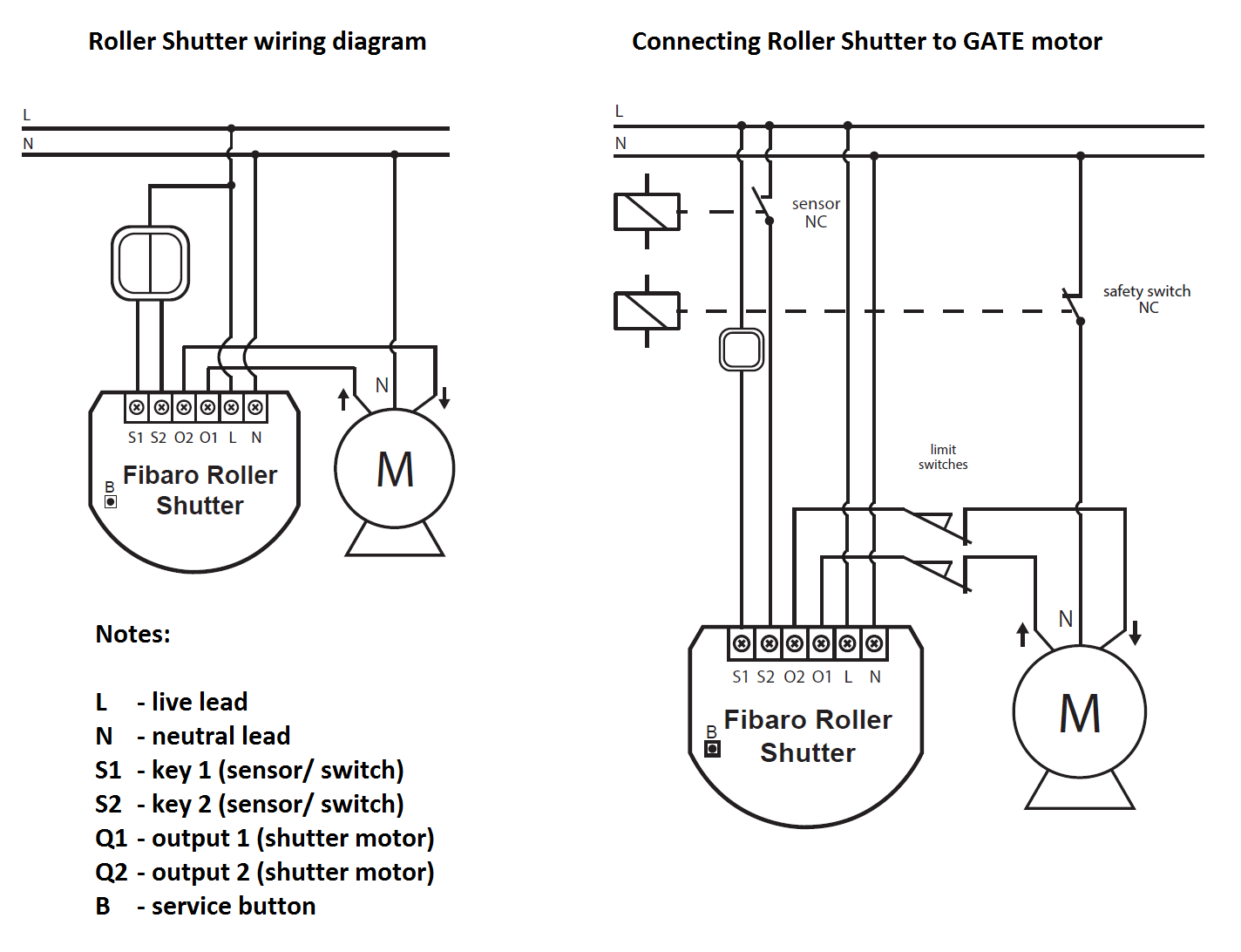
The motor control can be operated locally using a switching paddle installed on the wall box. To connect the switching paddle with the insert it has to be connected with the insert contacts S1, S2.
Attention: There must not be mains-power connected to the insert contacts. This would immediately lead to a destruction of the insert.
The local operation can be realized by a double switching paddle (bistable) or a double button (monostable). The connected switch type must be selected according to the inclusion by setting the configuration parameter 14. The local switch is connected with the motor control insert as shown in the schematics. If a bistable switch is connected it has to stay connected until the motor control insert is included into the Z-Wave network.
The Blind Control Insert 2 can also be used to control a Gate motor. Therefore it is necessery to install an additional safety switch NC and an sensor NC like shown in the figure.
Attention: The switch insert has an automatic endposition identification. This requires that the insert is connected with a tube motor with endposition switches. A test operation without motor leads to a wrong behavior.
It may be necessery to calibrate the module, when it"s not working properly. The Calibration is a process during which a Roller Shutter learns the position of the limit switches and a motor characteristic. The procedure consists of an automatic, full movement between the limit switches (up, down, and up again). There are different procedures of calibrating a Fibaro Roller Shutter.
Calibration:
Calibration through the Z-Wave network
- Make sure the module is connected to the power supply.
- Include the module into the Z-Wave network according to the inclusion procedure.
- Set the parameter 29 value to 1.
- Roller Shutter performs the calibration process, completing full cycle - up, down and up again.
- The parameter 29 value will be automatically set to 0.
- Using an interface test whether the positioning works correctly.
Calibration through the switch keys
- Make sure the module is connected to the power supply and to the switch keys as well (S1 and S2 inputs).
- Include the module into the Z-Wave network according to the inclusion procedure.
- Press and hold the switch key connected to S1 or S2 input terminal and release it after at least 3 seconds.
- Press and hold the same switch key again, and release it after 3 seconds.
- Now press and hold the same button, for 3 seconds, for the 3rd time.
- After pressing and releasing the button for the third time, automatic calibration sequence will start.
- Roller Shutter performs the calibration process, completing full cycle - up, down and up again.
Calibration through Menu (B-button)
- Make sure the module is connected to the power supply.
- Include the module into the Z-Wave network according to the inclusion procedure.
- Press and hold the B-button for ca. 6 seconds.
- LED will glow blue.
- Release the B-button and press it again, briefly.
- Roller Shutter performs the calibration process, completing full cycle - up, down and up again.
CALIBRATING LAMELLAS POSITIONING IN VENETIAN BLINDS
Apart from calibrating the roller blind position, it?s possible to calibrate the position of venetian blinds lamellas, in connection with a Fibaro Home Center 2. After correct calibration, in case of venetian blinds, it?s possible to set the position between the limit switches, as well as the lamellas angle. By default, time of full turn of the lamellas is set to 1,5 seconds. If necessary, it can be modified following below instructions.
- Make sure the module is connected to the power supply.
- Include the module into the Z-Wave network according to the inclusion procedure.
- Calibrate the Roller Shutter according to the instructions above.
- Set the parameter 10 value to 2 or choose in HC2 interface: Device Type - Venetian Blind
- Another device icon, responsible for lamellas operation, will show up in Home Center 2 interface. In case of any other Z-Wave network controllers managing the lamellas position is achieved through pressing and holding a switch key (up or down).
- By default, time of transition between extreme positions is set to 1.500 ms (1,5 seconds).
- Turn lamellas between extreme positions. If after full cycle a blind starts moving up or down, then parameter?s 12 value must be modified, e.g. to 1.000ms (1 second). Correctly configured lamellas should not force the blind to move up or down.
Product Usage
The Fibaro Blind Control Insert 2 has different operating modes. Each operating mode affects certain parameters settings:
- Roller blind without positioning (parameter 10 set to 0).
- Roller blind with positioning (parameter 10 set to 1).
- Venetian blind (parameter 10 set to 2; parameter 13, set to 2).
- Gate without positioning (parameter 10 set to 3; parameter 12 set to 0; parameter 17 set to 0).
- Gate with positioning (parameter 10 set to 4; parameter 12 set to 0; parameter 17 set to 0).
After chosing the operation mode the Fibaro Blind Control Insert 2 can be controlled with the Fibaro Home Center 2 or any other Z-Wave Primary Controller. Fibaro Roller Shutter allows for connecting push buttons to S1 and S2 terminals. These may be momentary or toggle switches, alternatively. Push buttons are responsible for managing the blind?s movement.
Using momentary switches:
Clicking UP button connected to S1 terminal, initiates up movement. Clicking button connected to S2 terminal, initiates down movement.
If the blind is moving, each click, of any button, will stop the movement. In addition a button click sends a command frame to I-st association group devices. In case of venetian blinds, it?s possible to manage the lamellas angle. Operating Mode - Venetian Blind, or Parameter 10 value set to 2.
Holding connected to S1 terminal initiates lamellas rotation up. Holding connected to S2 terminal initiates lamellas rotation down. In addition a button hold sends a Fibar Command Class control frame to II-nd association group devices.
Using toggle switches:
Changing switch key position, connected to S1 terminal, initiates up movement. Changing switch key position, connected to S2 terminal, initiates down movement. Choosing a middle position stops the blind.
| Reset to factory default | Reset procedure clears the modules? EPROM memory, including all information about the Z-Wave network controller, calibration and power consumption data. Resetting Blind Control Insert 2:
|
| Inclusion | To include the device into the network, turn the controller into the inclusion mode and then triple click the B-button or a push button connected to the S1 terminal. Further you can use the auto-inclusion mode by setting the controller into the inclusion mode and then connect voltage supply. The device is now ready to work. |
| Exclusion | To include the device into the network, turn the controller into the inclusion mode and then triple click the B-button or a push button connected to the S1 terminal. Further you can use the auto-inclusion mode by setting the controller into the inclusion mode and then connect voltage supply. The device is now ready to work. |
| NIF | XXXNIF |
| Wakeup | XXXWakeupDescription |
| Protection | XXXProtection |
| FirmwareUpdate | XXXFirmwareUpdate |
| SetAssociation | XXXSetAssociation |
Association Groups:
| Group Number | Maximum Nodes | Description |
|---|---|---|
| 3 | 1 | reports the module status; default setting primary controller |
| 2 | 16 | triggered through a momentary switch hold |
| 1 | 16 | triggered through a momentary switch click or a toggle switch position change |
Configuration Parameters
Parameter 1: local protection
enables/disables local entry. If activated module stops responding to S1 and S2 push buttons, SCENE ID and association commands will not be sent. Only exception is the B-button. Size: 1 Byte, Default Value: 00
| Setting | Description |
|---|---|
| 00 | 0 - no protection. Roller Shutter responds to push buttons. |
| 01 | 1 - not supported. |
| 02 | 2 - Local protection active. Roller Shutter does not respond to push buttons. |
Parameter 2: radio protection
enables/disables RF protection. If activated device stops responding to command frames. Configuration and polling still possible. Size: 1 Byte, Default Value: 00
| Setting | Description |
|---|---|
| 00 | 0 - No protection. Roller Shutter responds to command frames. |
| 01 | 1 - RF Protection active. Roller Shutter does not respond to the Z-Wave control frames. |
| 02 | 2 - not supported. |
Parameter 3: reports type
Parameters value shoud be set to 1 if the module operates in Venetian Blind mode. Size: 1 Byte, Default Value: 00
| Setting | Description |
|---|---|
| 00 | 0 - Blind position reports sent to the main controller using Z-Wave Command Class. |
| 01 | 1 - Blind position reports sent to the main controller using Fibar Command Class. |
Parameter 10: Roller Shutter operating modes
parameter sets the operating mode. Size: 1 Byte, Default Value: 01
| Setting | Description |
|---|---|
| 00 | 0 - Roller Blind Mode, without positioning |
| 01 | 1 - Roller Blind Mode, with positioning |
| 02 | 2 - Venetian Blind Mode, with positioning |
| 03 | 3 - Gate Mode, without positioning |
| 04 | 4 - Gate Mode, with positioning |
Parameter 12: turning time/ delay time
In Venetian Blind mode (parameter 10 set to 2) the parameter determines time of full turn of the lamellas. In Gate Mode (parameter 10 set to 3 or 4) the parameter defines the delay time after which an open gate starts closing. Size: 2 Byte, Default Value: 0096
| Setting | Description |
|---|
Parameter 13: lamellas positioning mode
parameter influences the lamellas positioning in venetian blind mode (parameter 10 set to 2) Size: 1 Byte, Default Value: 01
| Setting | Description |
|---|---|
| 00 | 0 - Lamellas return to previously set position only in case of the main controller operation. |
| 01 | 1 - Lamellas return to previously set position in case of the main controller operation, momentary switch operation, or when the limit switch is reached. |
| 02 | 2 - Lamellas return to previously set position in case of the main controller operation, momentary switch operation, when the limit switch is reached or after receiving a u201cSTOPu201d control frame (Switch Multilevel Stop). |
Parameter 14: switch type
parameter settings are relevant for Roller Blind Mode and Venetian Blind Mode (parameter 10 set to 0, 1, 2). Size: 1 Byte, Default Value: 00
| Setting | Description |
|---|---|
| 00 | 0 - Momentary switches |
| 01 | 1 - Toggle switches |
| 02 | 2 - Single, momentary switch. (The switch should be connected to S1 terminal) |
Parameter 17: delay time after S2
In roller blind mode or venetian blind mode (parameter 10 set to 0, 1, 2) the parameter determines when the Roller Shutter relays are turned off after reaching a limit switch. In Gate Mode (parameter 10 set to 3 or 4) the parameter determines a time period after which a gate will start closing after a S2 contact has been disconnected. Size: 1 Byte, Default Value: 0a
| Setting | Description |
|---|
Parameter 18: motor operation detection
Power threshold to be interpreted as reaching a limit switch. Size: 1 Byte, Default Value: 0a
| Setting | Description |
|---|
Parameter 22: motor operation time
Time period for the motor to continue operation. Size: 2 Byte, Default Value: 00f0
| Setting | Description |
|---|
Parameter 29: Forced Roller Shutter calibration
seting the parameter to 1 Roller Shutter enters the calibration mode. Parameteronly is only relevant if a Roller Shutter is set to work in positioning mode (parameter 10 set to 1, 2 or 4). Size: 1 Byte, Default Value: 00
| Setting | Description |
|---|---|
| 00 | 0 - deactivated (value 0 is automatically set after calibration process) |
| 01 | 1 - Start calibration process |
Parameter 30: Response to general alarm
Size: 1 Byte, Default Value: 02
| Setting | Description |
|---|---|
| 00 | 0 - No reaction. |
| 01 | 1 - Open blind. |
| 02 | 2 - Close blind. |
Parameter 31: Response to flooding alarm
Size: 1 Byte, Default Value: 00
| Setting | Description |
|---|---|
| 00 | 0 - No reaction. |
| 01 | 1 - Open blind. |
| 02 | 2 - Close blind. |
Parameter 32: Response to smoke, CO or CO2 alarm
Size: 1 Byte, Default Value: 01
| Setting | Description |
|---|---|
| 00 | 0 - No reaction. |
| 01 | 1 - Open blind. |
| 02 | 2 - Close blind. |
Parameter 33: Response to temperature alarm
Size: 1 Byte, Default Value: 01
| Setting | Description |
|---|---|
| 00 | 0 - No reaction. |
| 01 | 1 - Open blind. |
| 02 | 2 - Close blind. |
Parameter 35: Managing lamellas in response to alarm
In Venetian Blind Mode (parameter 10 set to 2), the parameter determines how the lamellas will react upon alarm detection. Size: 1 Byte, Default Value: 01
| Setting | Description |
|---|---|
| 00 | 0 - Do not change lamellas position - lamellas return to the last set position. |
| 01 | 1 - Set lamellas to their extreme position. |
Parameter 40: Power reports
Power level change that will result in new power value report being sent. value is a percentage of the previous report. Size: 1 Byte, Default Value: 0a
| Setting | Description |
|---|
Parameter 42: Periodic power or energy reports
time to the next report Size: 2 Byte, Default Value: 0e10
| Setting | Description |
|---|
Parameter 43: Energy reports
Energy level change which will result in new energy value report being sent. Size: 1 Byte, Default Value: 0a
| Setting | Description |
|---|
Parameter 44: Self-measurement
enables/disables to include the power and energy used by itself in reports to main controller. Size: 1 Byte, Default Value: 00
| Setting | Description |
|---|---|
| 00 | 0 - Self-measurement inactive. |
| 01 | 1 - Self-measurement active. |
Parameter 50: Scenes/ Associations activation
Parameter determines whether scenes or associations are activated by the switch keys. Size: 1 Byte, Default Value: 00
| Setting | Description |
|---|---|
| 00 | 0 - Associations activation |
| 01 | 1 - Scenes activation |
Technical Data
| Dimensions | 0.0420000x0.0370000x0.0160000 mm |
| Weight | 26 gr |
| EAN | 5902020528227 |
| Device Type | Window Covering Endpoint Aware |
| Generic Device Class | Multilevel Switch |
| Specific Device Class | Motor Control Device (B) |
| Firmware Version | 16.16 |
| Z-Wave Version | 03.34 |
| Certification ID | ZC08-11080006 |
| Z-Wave Product Id | 010f.0301.1001 |
| Frequency | Europe - 868,4 Mhz |
| Maximum transmission power | 5 mW |