Everspring
OUTDOOR MOTION DETECTOR
SKU: EVRESP816


Quickstart
This is a
Important safety information
Please read this manual carefully. Failure to follow the recommendations in this manual may be dangerous or may violate the law. The manufacturer, importer, distributor and seller shall not be liable for any loss or damage resulting from failure to comply with the instructions in this manual or any other material. Use this equipment only for its intended purpose. Follow the disposal instructions. Do not dispose of electronic equipment or batteries in a fire or near open heat sources.What is Z-Wave?
Z-Wave is the international wireless protocol for communication in the Smart Home. This device is suited for use in the region mentioned in the Quickstart section.
Z-Wave ensures a reliable communication by reconfirming every message (two-way communication) and every mains powered node can act as a repeater for other nodes (meshed network) in case the receiver is not in direct wireless range of the transmitter.
This device and every other certified Z-Wave device can be used together with any other certified Z-Wave device regardless of brand and origin as long as both are suited for the same frequency range.
If a device supports secure communication it will communicate with other devices secure as long as this device provides the same or a higher level of security. Otherwise it will automatically turn into a lower level of security to maintain backward compatibility.
For more information about Z-Wave technology, devices, white papers etc. please refer to www.z-wave.info.
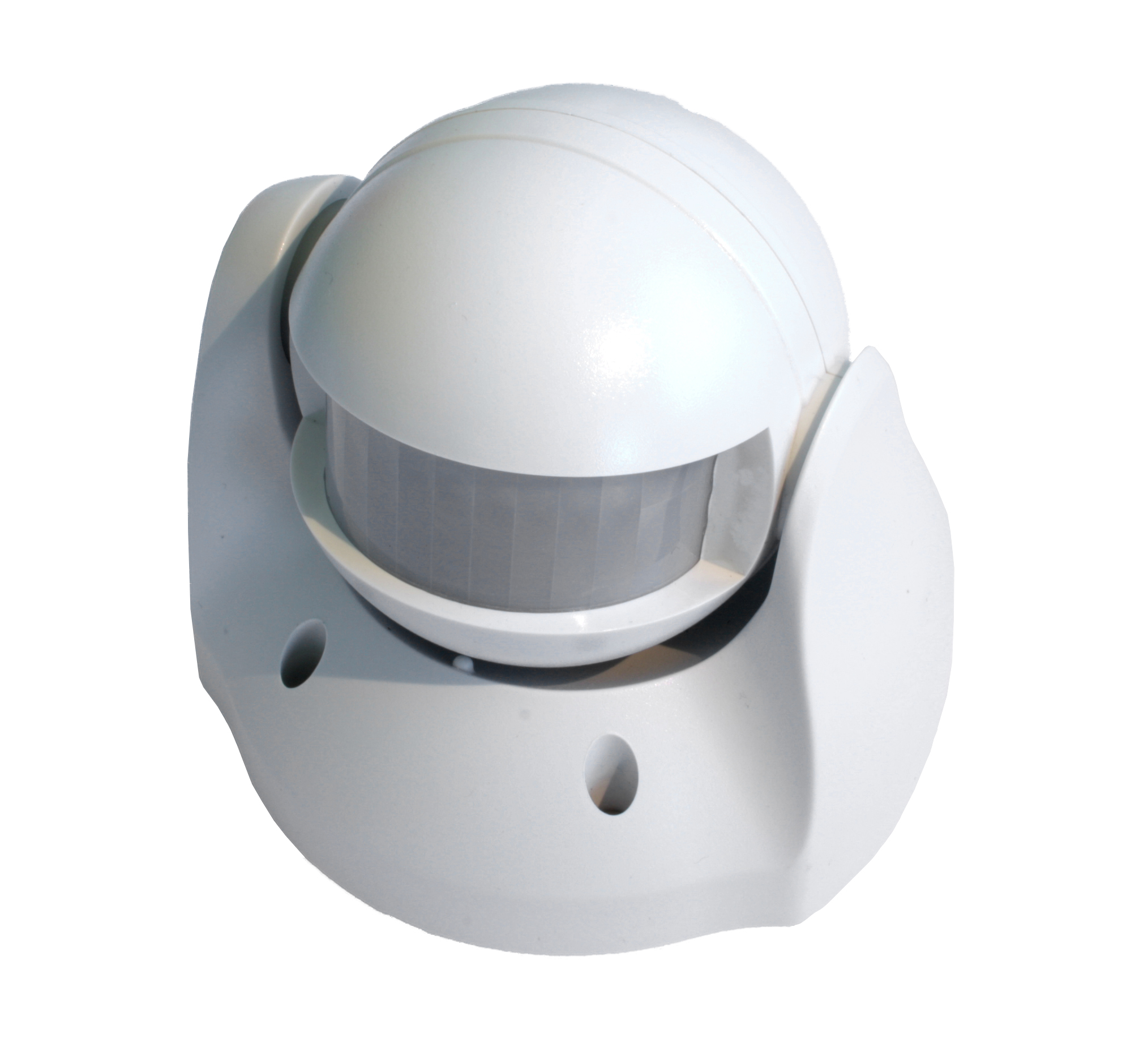
Product Description
This motion detector is primarily designed for outdoor lighting control application. It features a PIR motion detector to detect movement in a protected area and a lux sensor for determining brightness of its surroundings. It comes with a built in timer to set the duration for light turn on. The lux level and the timer can be set through knobs on the device itself.
If the PIR detects motion when lux level falls below a preset setting, the device will transmit a signal to turn on the outdoor lighting (or indirectly through gateway) and then later turns it off when its timer has elapsed.
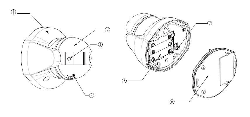
6 Rear Cover
7 Tamper Switch
Prepare for Installation / Reset
Please read the user manual before installing the product.
In order to include (add) a Z-Wave device to a network it must be in factory default state. Please make sure to reset the device into factory default. You can do this by performing an Exclusion operation as described below in the manual. Every Z-Wave controller is able to perform this operation however it is recommended to use the primary controller of the previous network to make sure the very device is excluded properly from this network.
Reset to factory default
This device also allows to be reset without any involvement of a Z-Wave controller. This procedure should only be used when the primary controller is inoperable.
Safety Warning for Batteries
The product contains batteries. Please remove the batteries when the device is not used. Do not mix batteries of different charging level or different brands.
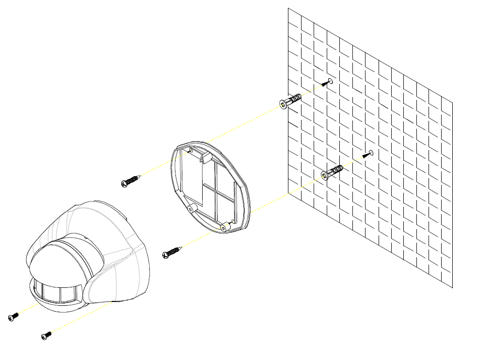
Installation
Inclusion/Exclusion
On factory default the device does not belong to any Z-Wave network. The device needs to be added to an existing wireless network to communicate with the devices of this network. This process is called Inclusion.
Devices can also be removed from a network. This process is called Exclusion. Both processes are initiated by the primary controller of the Z-Wave network. This controller is turned into exclusion respective inclusion mode. Inclusion and Exclusion is then performed doing a special manual action right on the device.
Inclusion
Exclusion
Auto-Inclusion
Beside the standard inclusion this devices supports the so called auto inclusion. Right after powering up the device remains in inclusion state and can be included by (any) gateway without further actions on the device itself. The auto inclusion mode will time out after some time.Product Usage
2. During Test mode, if movement is detected, the LED on the detector will illuminate implying the unit is working properly.


When the detector is mounted on the wall, i.e. tamper switch is pressed, for more than 10 seconds, it will enter Normal mode.
(1) Time adjustment

(2) Lux adjustment

Quick trouble shooting
Here are a few hints for network installation if things dont work as expected.
- Make sure a device is in factory reset state before including. In doubt exclude before include.
- If inclusion still fails, check if both devices use the same frequency.
- Remove all dead devices from associations. Otherwise you will see severe delays.
- Never use sleeping battery devices without a central controller.
- Dont poll FLIRS devices.
- Make sure to have enough mains powered device to benefit from the meshing
Association - one device controls an other device
Z-Wave devices control other Z-Wave devices. The relationship between one device controlling another device is called association. In order to control a different device, the controlling device needs to maintain a list of devices that will receive controlling commands. These lists are called association groups and they are always related to certain events (e.g. button pressed, sensor triggers, ...). In case the event happens all devices stored in the respective association group will receive the same wireless command wireless command, typically a 'Basic Set' Command.
Association Groups:
| Group Number | Maximum Nodes | Description |
|---|---|---|
| 1 | 1 | Lifeline |
| 2 | 4 | PIR Control - Basic Set |
Technical Data
| Dimensions | 0.0990000x0.0940000x0.0950000 mm |
| Weight | 243 gr |
| Hardware Platform | ZM5202 |
| EAN | 4713616113359 |
| IP Class | IP 44 |
| Battery Type | 3 * AA 1,5V |
| Device Type | Motion Sensor |
| Firmware Version | 01.01 |
| Z-Wave Version | 04.3d |
| Certification ID | ZC08-13080009 |
| Z-Wave Product Id | 0x0060.0x0001.0x0005 |
| Frequency | Europe - 868,4 Mhz |
| Maximum transmission power | 5 mW |
Supported Command Classes
- Basic
- Association Grp Info
- Device Reset Locally
- Zwaveplus Info
- Alarm
- Manufacturer Specific
- Powerlevel
- Firmware Update Md
- Battery
- Wake Up
- Association
- Version
- Security
- Transport Service
- Security 2
Controlled Command Classes
- Transport Service
- Security 2
Explanation of Z-Wave specific terms
- Controller — is a Z-Wave device with capabilities to manage the network. Controllers are typically Gateways,Remote Controls or battery operated wall controllers.
- Slave — is a Z-Wave device without capabilities to manage the network. Slaves can be sensors, actuators and even remote controls.
- Primary Controller — is the central organizer of the network. It must be a controller. There can be only one primary controller in a Z-Wave network.
- Inclusion — is the process of adding new Z-Wave devices into a network.
- Exclusion — is the process of removing Z-Wave devices from the network.
- Association — is a control relationship between a controlling device and a controlled device.
- Wakeup Notification — is a special wireless message issued by a Z-Wave device to announces that is able to communicate.
- Node Information Frame — is a special wireless message issued by a Z-Wave device to announce its capabilities and functions.