Aquascope
Custos Wirless Water Sensor
SKU: AQUEWWDZWE


Quickstart
This is a
This device supports Z-Wave Smart Start. Please scan the QR Code on the device label before adding if your gateway supporting Smart Start. Connect the water pins for 6+ seconds to enter smart start inclusion mode. Blinking green LED will indicate the device has entered smart start. Now disconnect the water pins and device is in smart start mode. During smart start mode you can still use the classic inclusion operation with 2 seconds connecting water pins.
Important safety information
Please read this manual carefully. Failure to follow the recommendations in this manual may be dangerous or may violate the law. The manufacturer, importer, distributor and seller shall not be liable for any loss or damage resulting from failure to comply with the instructions in this manual or any other material. Use this equipment only for its intended purpose. Follow the disposal instructions. Do not dispose of electronic equipment or batteries in a fire or near open heat sources.Product Description
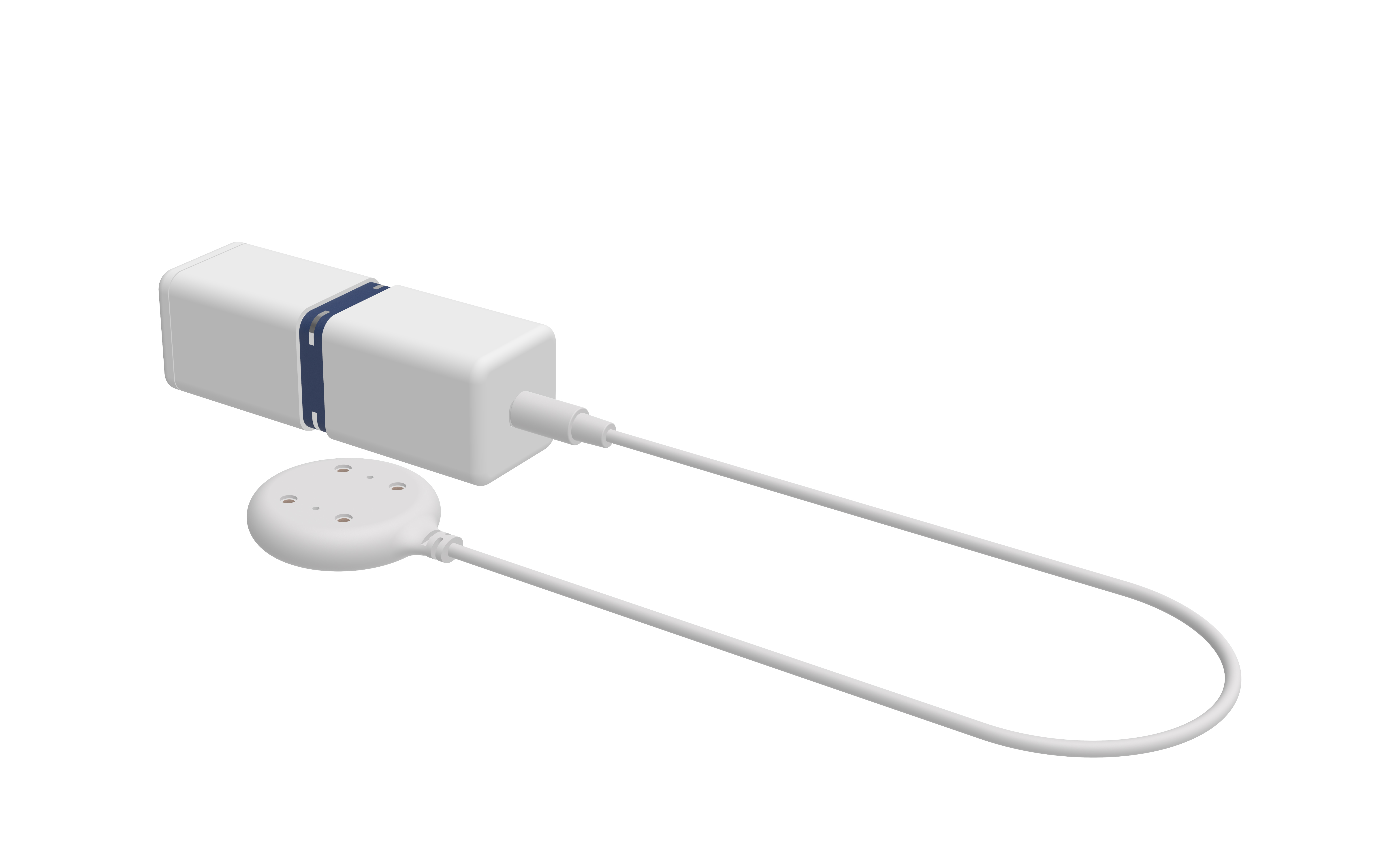
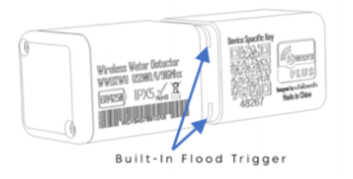
The Water Contact Sensor is placed on critical positions within the home and will detect even smallest drops of water thanks to the capillary effect (water is soaked into the colored sensor channel). Detected water results in an alarm sent to a central gateway using Z-Wave wireless protocol. The unique feature of this device is the central sensor ring with 4 metal water probes on four corners. This ensures the detection works in all possible orientations of the device. An external second water detection probe can be connected to the main device and it will act as second sensor differing from the primary sensor probe inside the ring. The internal temperature sensor will report freezing condition to protect water installation from further damaging.
Installation
The device can be installed on any place inside or outside the home. It will work in any position (except upright) since it has 4 sensing pins. The sensing pins as positioned in a way that even minimal water will be soaked under the device and generate an alert.
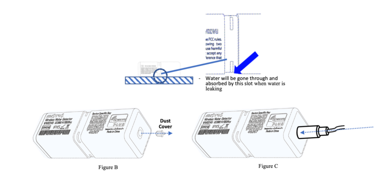
There is an optional remote sensing pin connected by cable to the main device. Remove the protection rubber and plug in the cable if you want to use this function. Make sure the jack is fully inserted into the opening.

The built-in battery shall last 7 years or longer but even this long time comes to an end. To replace the battery open the compartment by removing the two screws as shown in the picture below. Make sure the rubber gasket is in place when closing the battery compartment.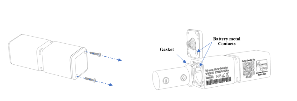
Product Usage
The device has the following built-in sensors that send values to the Gateway when connected.
- Temperature Sensor Value
- Temperature Overheat Alarm (0x04-0x02, heat detected)
- Water Leak Alarm (0x05- 0x02 leak detected)
Water leaks alarms are caused either by the internal sensor pins on by the colored ring or the optionally attached sensor pad.
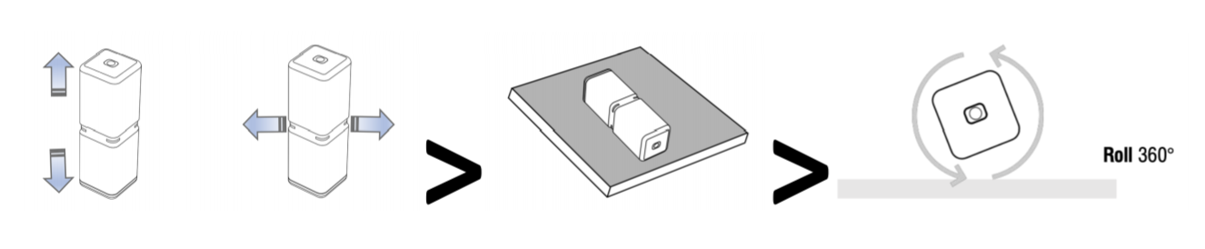
| Reset to factory default | This device is controlled by motion.
1. Shake the device for few seconds and place it flat on the table.
2. Wait for two buzzer sounds with two times green LED. This indicates the device is ready for gesture. Red/Yellow blinking LED shows readiness. 3. Now rotate the device 360 degree while keeping it on the table.
 |
| Inclusion | 1. When in factory reset connect two of the pins in the ring (using a wire or water or two wet fingers) for two seconds. Short beeps and yellow LED help counting. |
| Exclusion | Devices can also be removed from a network. Both processes are initiated by the primary controller of the Z-Wave network. This controller is turned into inclusion respective exclusion mode. Removing works only when the device is included in a network and active. 1. Shake the device for few seconds and place it flat on the table.2. Wait for two buzzer sounds with two times green LED. This indicates the device is ready for gesture. Red/Yellow blinking LED shows readiness. 3. Now Turn the device in upright position. 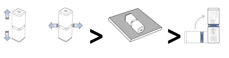 |
| NIF | XXXNIF |
| Wakeup | XXXWakeupDescription |
| Protection | XXXProtection |
| FirmwareUpdate | XXXFirmwareUpdate |
| SetAssociation | XXXSetAssociation |
Association Groups:
| Group Number | Maximum Nodes | Description |
|---|---|---|
| 1 | 5 | Lifeline |
| 2 | 5 | Switch Devices when Built-In Leak Sensor alerts |
| 3 | 5 | Switch Devices when Remote Leak Sensor Pad alerts |
| 4 | 5 | Switch Devices when temperature raise above threshold |
| 5 | 5 | Switch Devices when temperature falls below threshold |
Configuration Parameters
Parameter 16: Sensor Functions
This parameter defines which sensor function of the device is active Size: 1 Byte, Default Value: 15
| Setting | Description |
|---|---|
| 1 | Built-In Detection Probe |
| 2 | Remote Water Detection Probe |
| 4 | Overhead Detection |
| 8 | Freeze Detection |
Parameter 17: Water Leak Cancelation Command Behavior
Defines when a BASIC command Value to send to cancel water alarm Size: 1 Byte, Default Value: 1
| Setting | Description |
|---|---|
| 0 | Send BASIC SET command when Water Alarm canceled either Built-In OR on Remote Probe |
| 1 | Send BASIC SET command when Water Alarm canceled on Built-In AND on Remote Probe |
Parameter 48: Temperature Sensor Report
Defines if and how a temperature value is reported Size: 1 Byte, Default Value: 1
| Setting | Description |
|---|---|
| 0 | Disabled |
| 1 | Report in Celsius |
| 2 | Report in Fahrenheit |
Parameter 49: Temperature Sensor Report Threshold
Defines the change in temperature value to cause unsolicited sending of an report. Size: 1 Byte, Default Value: 1
| Setting | Description |
|---|---|
| 0 - 255 | Value in Celsius (example: 2 = 2 °C) |
| 256 - 511 | Value in Fahrenheit (example: 258 = 2 °F) |
Parameter 50: Temperature Sensor Report Offset
Defines a temperature offset for the reported temperature. This parameter can be used to compensate for certain temperature deviations. Size: 2 Byte, Default Value: 0
| Setting | Description |
|---|---|
| 0 - 255 | Positive Deviation in Celsius (e.g. 2 = +2 °C) |
| 4096 - 4351 | Negative Deviation in Celsius (e.g. 4097 = -2 °C) |
| 256 - 511 | Positive Deviation in Fahrenheit (e.g. 258 = +2 °F) |
| 4352 - 4607 | Negative Deviation in Fahrenheit (e.g. 4353 = -2 °F) |
Parameter 51: Temperature Overheat Trigger
Sets the temperature to trigger and overheat alarm Size: 2 Byte, Default Value: 40
| Setting | Description |
|---|---|
| 0 - 255 | Value in Celsius (example: 2 = 2 °C) |
| 256 - 511 | Value in Fahrenheit (example: 25 = 2 °F) |
Parameter 52: Temperature Overheat Reset Trigger Value
Sets the temperature to reset the overheat alarm Size: 2 Byte, Default Value: 30
| Setting | Description |
|---|---|
| 0 - 255 | Value in Celsius (example: 0x02 = 2 °C) |
| 256 - 511 | Value in Fahrenheit (example: 0x102 = 2 °F) |
Parameter 53: Freeze Trigger Value
Sets the temperature threshold to cause a freeze alarm Size: 2 Byte, Default Value: 0
| Setting | Description |
|---|---|
| 0 - 255 | Value in Celsius (example: 2 = 2 °C) |
| 256 - 511 | Value in Fahrenheit (example: 258 = 2 °F) |
Parameter 54: Freeze Trigger Reset Value
Sets the temperature threshold to reset a freeze alarm Size: 2 Byte, Default Value: 2
| Setting | Description |
|---|---|
| 0 - 255 | Value in Celsius (example: 2 = 2 °C) |
| 256 - 511 | Value in Fahrenheit (example: 258 = 2 °F) |
Parameter 64: Built-In Leak Detection Command Value
Defines what BASIC command Value to send into Association Group 2 Size: 1 Byte, Default Value: 1
| Setting | Description |
|---|---|
| 0 | Disable |
| 1 | Enabled Basic On (0xff) |
| 2 | Enabled, Basic Off (0x00) |
Parameter 65: Built-In Leak Detection Reset Command Value
Defines what BASIC command Value to send into Association Group 2 Size: 1 Byte, Default Value: 2
| Setting | Description |
|---|---|
| 0 | Disable |
| 1 | Enabled Basic On (0xff) |
| 2 | Enabled Basic Off (0x00) |
Parameter 66: Remote Leak Detection Command Value
Defines what BASIC command Value to send into Association Group 3 Size: 1 Byte, Default Value: 1
| Setting | Description |
|---|---|
| 0 | Disable |
| 1 | Enabled Basic On (0xff) |
| 2 | Enabled Basic Off (0x00) |
Parameter 67: Remote Leak Detection Reset Command Value
Defines what BASIC command Value to send into Association Group 3 Size: 1 Byte, Default Value: 2
| Setting | Description |
|---|---|
| 0 | Disable |
| 1 | Enabled Basic On (0xff) |
| 2 | Enabled Basic Off (0x00) |
Parameter 68: Temperature Overhead Action Value
Defines what BASIC command Value to send into Association Group 4 Size: 1 Byte, Default Value: 0
| Setting | Description |
|---|---|
| 0 | Disable |
| 1 | Enabled Basic On (0xff) |
| 2 | Enabled Basic Off (0x00) |
Parameter 69: Temperature Overhead Action Reset Value
Defines what BASIC command Value to send into Association Group 4 Size: 1 Byte, Default Value: 0
| Setting | Description |
|---|---|
| 0 | Disable |
| 1 | Enabled Basic On (0xff) |
| 2 | Enabled Basic Off (0x00) |
Parameter 70: Freeze Association Action Command
Defines what BASIC command Value to send into Association Group 5 Size: 1 Byte, Default Value: 0
| Setting | Description |
|---|---|
| 0 | Disable |
| 1 | Enabled Basic On (0xff) |
| 2 | Enabled Basic Off (0x00) |
Parameter 71: Freeze Association Reset Command
Defines what BASIC command Value to send into Association Group 5 Size: 1 Byte, Default Value: 0
| Setting | Description |
|---|---|
| 0 | Disable |
| 1 | Enabled Basic On (0xff) |
| 2 | Enabled Basic Off (0x00) |
Parameter 80: Resent Water Leak Notification time
Defines the interval of resending water leak notification if the water is still present Size: 1 Byte, Default Value: 0
| Setting | Description |
|---|---|
| 0 | Disable |
| 1 - 30 | Minutes |
Technical Data
| Dimensions | 23x23x68 mm |
| Weight | 27 gr |
| Hardware Platform | ZGM130 |
| EAN | 4897105830061 |
| IP Class | IP IP 66 |
| Voltage | 3V |
| Battery Type | 1 * ER14250 |
| Device Type | Sensor-Notification |
| Network Operation | Sensor |
| Firmware Version | 02.01 |
| Z-Wave Version | 07.13.2 |
| Z-Wave Product Id | 0270.0004.010b |
| Frequency | Europe - 868,4 Mhz |
| Maximum transmission power | 5 mW |