Aquascope
Custos Wirless Water Sensor
SKU: AQUEWWDZWE


Quickstart
This is a
This device supports Z-Wave Smart Start. Please scan the QR Code on the device label before adding if your gateway supporting Smart Start. Connect the water pins for 6+ seconds to enter smart start inclusion mode. Blinking green LED will indicate the device has entered smart start. Now disconnect the water pins and device is in smart start mode. During smart start mode you can still use the classic inclusion operation with 2 seconds connecting water pins.
Important safety information
Please read this manual carefully. Failure to follow the recommendations in this manual may be dangerous or may violate the law. The manufacturer, importer, distributor and seller shall not be liable for any loss or damage resulting from failure to comply with the instructions in this manual or any other material. Use this equipment only for its intended purpose. Follow the disposal instructions. Do not dispose of electronic equipment or batteries in a fire or near open heat sources.What is Z-Wave?
Z-Wave is the international wireless protocol for communication in the Smart Home. This device is suited for use in the region mentioned in the Quickstart section.
Z-Wave ensures a reliable communication by reconfirming every message (two-way communication) and every mains powered node can act as a repeater for other nodes (meshed network) in case the receiver is not in direct wireless range of the transmitter.
This device and every other certified Z-Wave device can be used together with any other certified Z-Wave device regardless of brand and origin as long as both are suited for the same frequency range.
If a device supports secure communication it will communicate with other devices secure as long as this device provides the same or a higher level of security. Otherwise it will automatically turn into a lower level of security to maintain backward compatibility.
For more information about Z-Wave technology, devices, white papers etc. please refer to www.z-wave.info.
Product Description
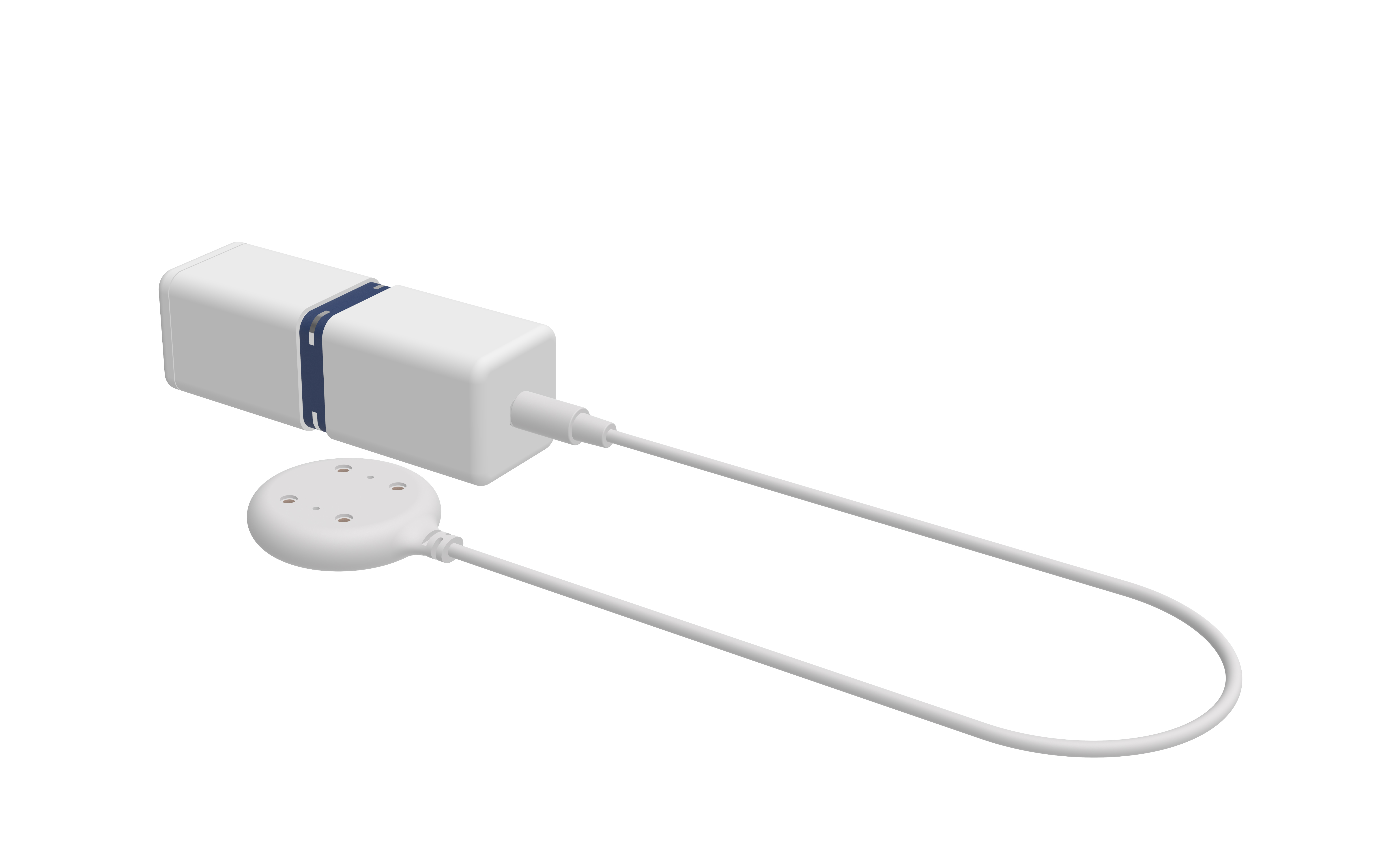
The Water Contact Sensor is placed on critical positions within the home and will detect even smallest drops of water thanks to the capillary effect (water is soaked into the colored sensor channel). Detected water results in an alarm sent to a central gateway using Z-Wave wireless protocol. The unique feature of this device is the central sensor ring with 4 metal water probes on four corners. This ensures the detection works in all possible orientations of the device. An external second water detection probe can be connected to the main device and it will act as second sensor differing from the primary sensor probe inside the ring. The internal temperature sensor will report freezing condition to protect water installation from further damaging.
Prepare for Installation / Reset
Please read the user manual before installing the product.
In order to include (add) a Z-Wave device to a network it must be in factory default state. Please make sure to reset the device into factory default. You can do this by performing an Exclusion operation as described below in the manual. Every Z-Wave controller is able to perform this operation however it is recommended to use the primary controller of the previous network to make sure the very device is excluded properly from this network.
Reset to factory default
This device also allows to be reset without any involvement of a Z-Wave controller. This procedure should only be used when the primary controller is inoperable.
2. Wait for two buzzer sounds with two times green LED. This indicates the device is ready for gesture. Red/Yellow blinking LED shows readiness.
Safety Warning for Batteries
The product contains batteries. Please remove the batteries when the device is not used. Do not mix batteries of different charging level or different brands.
Installation
The device can be installed on any place inside or outside the home. It will work in any position (except upright) since it has 4 sensing pins. The sensing pins as positioned in a way that even minimal water will be soaked under the device and generate an alert.
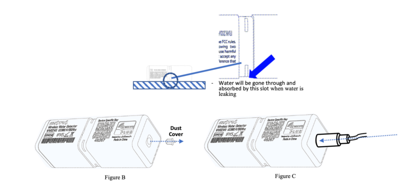
There is an optional remote sensing pin connected by cable to the main device. Remove the protection rubber and plug in the cable if you want to use this function. Make sure the jack is fully inserted into the opening.

The built-in battery shall last 7 years or longer but even this long time comes to an end. To replace the battery open the compartment by removing the two screws as shown in the picture below. Make sure the rubber gasket is in place when closing the battery compartment.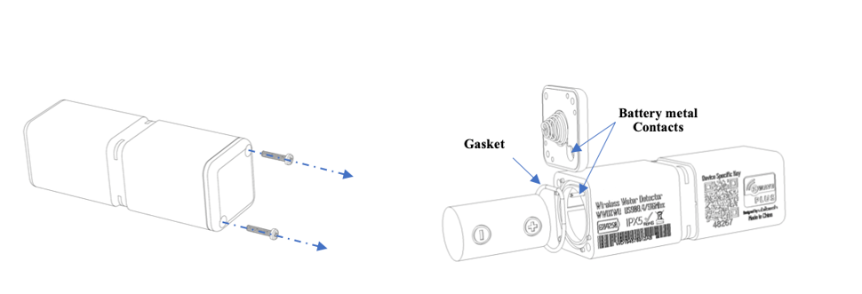
Inclusion/Exclusion
On factory default the device does not belong to any Z-Wave network. The device needs to be added to an existing wireless network to communicate with the devices of this network. This process is called Inclusion.
Devices can also be removed from a network. This process is called Exclusion. Both processes are initiated by the primary controller of the Z-Wave network. This controller is turned into exclusion respective inclusion mode. Inclusion and Exclusion is then performed doing a special manual action right on the device.
Inclusion
1. When in factory reset connect two of the pins in the ring (using a wire or water or two wet fingers) for two seconds. Short beeps and yellow LED help counting.
2. After two beeps release connection. This process only works when the device is in factory reset state.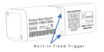
When using Smart start just scan the QR code on your device. Wakeup the device by connecting two of the pins for 5 seconds.
Exclusion
Devices can also be removed from a network. Both processes are initiated by the primary controller of the Z-Wave network. This controller is turned into inclusion respective exclusion mode. Removing works only when the device is included in a network and active.
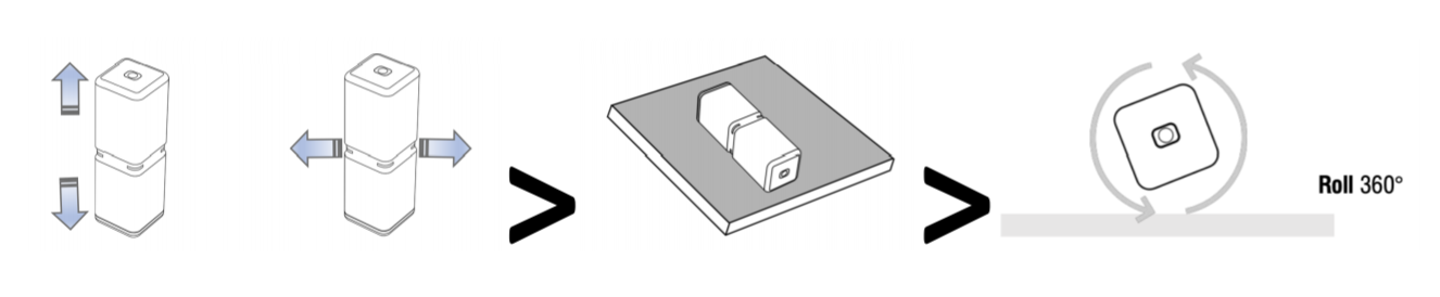
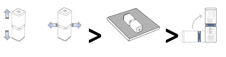
1. Shake the device for few seconds and place it flat on the table.2. Wait for two buzzer sounds with two times green LED. This indicates the device is ready for gesture. Red/Yellow blinking LED shows readiness.
3. Now Turn the device in upright position.
Product Usage
The device has the following built-in sensors that send values to the Gateway when connected.
- Temperature Sensor Value
- Temperature Overheat Alarm (0x04-0x02, heat detected)
- Water Leak Alarm (0x05- 0x02 leak detected)
Water leaks alarms are caused either by the internal sensor pins on by the colored ring or the optionally attached sensor pad.
Quick trouble shooting
Here are a few hints for network installation if things dont work as expected.
- Make sure a device is in factory reset state before including. In doubt exclude before include.
- If inclusion still fails, check if both devices use the same frequency.
- Remove all dead devices from associations. Otherwise you will see severe delays.
- Never use sleeping battery devices without a central controller.
- Dont poll FLIRS devices.
- Make sure to have enough mains powered device to benefit from the meshing
Association - one device controls an other device
Z-Wave devices control other Z-Wave devices. The relationship between one device controlling another device is called association. In order to control a different device, the controlling device needs to maintain a list of devices that will receive controlling commands. These lists are called association groups and they are always related to certain events (e.g. button pressed, sensor triggers, ...). In case the event happens all devices stored in the respective association group will receive the same wireless command wireless command, typically a 'Basic Set' Command.
Association Groups:
| Group Number | Maximum Nodes | Description |
|---|---|---|
| 1 | 5 | Lifeline |
| 2 | 5 | Switch Devices when Built-In Leak Sensor alerts |
| 3 | 5 | Switch Devices when Remote Leak Sensor Pad alerts |
| 4 | 5 | Switch Devices when temperature raise above threshold |
| 5 | 5 | Switch Devices when temperature falls below threshold |
Configuration Parameters
Z-Wave products are supposed to work out of the box after inclusion, however certain configuration can adapt the function better to user needs or unlock further enhanced features.
IMPORTANT: Controllers may only allow configuring signed values. In order to set values in the range 128 ... 255 the value sent in the application shall be the desired value minus 256. For example: To set a parameter to 200 it may be needed to set a value of 200 minus 256 = minus 56. In case of a two byte value the same logic applies: Values greater than 32768 may needed to be given as negative values too.
Parameter 16: Sensor Functions
This parameter defines which sensor function of the device is active Size: 1 Byte, Default Value: 15
| Setting | Description |
|---|---|
| 1 | Built-In Detection Probe |
| 2 | Remote Water Detection Probe |
| 4 | Overhead Detection |
| 8 | Freeze Detection |
Parameter 17: Water Leak Cancelation Command Behavior
Defines when a BASIC command Value to send to cancel water alarm Size: 1 Byte, Default Value: 1
| Setting | Description |
|---|---|
| 0 | Send BASIC SET command when Water Alarm canceled either Built-In OR on Remote Probe |
| 1 | Send BASIC SET command when Water Alarm canceled on Built-In AND on Remote Probe |
Parameter 48: Temperature Sensor Report
Defines if and how a temperature value is reported Size: 1 Byte, Default Value: 1
| Setting | Description |
|---|---|
| 0 | Disabled |
| 1 | Report in Celsius |
| 2 | Report in Fahrenheit |
Parameter 49: Temperature Sensor Report Threshold
Defines the change in temperature value to cause unsolicited sending of an report. Size: 1 Byte, Default Value: 1
| Setting | Description |
|---|---|
| 0 - 255 | Value in Celsius (example: 2 = 2 °C) |
| 256 - 511 | Value in Fahrenheit (example: 258 = 2 °F) |
Parameter 50: Temperature Sensor Report Offset
Defines a temperature offset for the reported temperature. This parameter can be used to compensate for certain temperature deviations. Size: 2 Byte, Default Value: 0
| Setting | Description |
|---|---|
| 0 - 255 | Positive Deviation in Celsius (e.g. 2 = +2 °C) |
| 4096 - 4351 | Negative Deviation in Celsius (e.g. 4097 = -2 °C) |
| 256 - 511 | Positive Deviation in Fahrenheit (e.g. 258 = +2 °F) |
| 4352 - 4607 | Negative Deviation in Fahrenheit (e.g. 4353 = -2 °F) |
Parameter 51: Temperature Overheat Trigger
Sets the temperature to trigger and overheat alarm Size: 2 Byte, Default Value: 40
| Setting | Description |
|---|---|
| 0 - 255 | Value in Celsius (example: 2 = 2 °C) |
| 256 - 511 | Value in Fahrenheit (example: 25 = 2 °F) |
Parameter 52: Temperature Overheat Reset Trigger Value
Sets the temperature to reset the overheat alarm Size: 2 Byte, Default Value: 30
| Setting | Description |
|---|---|
| 0 - 255 | Value in Celsius (example: 0x02 = 2 °C) |
| 256 - 511 | Value in Fahrenheit (example: 0x102 = 2 °F) |
Parameter 53: Freeze Trigger Value
Sets the temperature threshold to cause a freeze alarm Size: 2 Byte, Default Value: 0
| Setting | Description |
|---|---|
| 0 - 255 | Value in Celsius (example: 2 = 2 °C) |
| 256 - 511 | Value in Fahrenheit (example: 258 = 2 °F) |
Parameter 54: Freeze Trigger Reset Value
Sets the temperature threshold to reset a freeze alarm Size: 2 Byte, Default Value: 2
| Setting | Description |
|---|---|
| 0 - 255 | Value in Celsius (example: 2 = 2 °C) |
| 256 - 511 | Value in Fahrenheit (example: 258 = 2 °F) |
Parameter 64: Built-In Leak Detection Command Value
Defines what BASIC command Value to send into Association Group 2 Size: 1 Byte, Default Value: 1
| Setting | Description |
|---|---|
| 0 | Disable |
| 1 | Enabled Basic On (0xff) |
| 2 | Enabled, Basic Off (0x00) |
Parameter 65: Built-In Leak Detection Reset Command Value
Defines what BASIC command Value to send into Association Group 2 Size: 1 Byte, Default Value: 2
| Setting | Description |
|---|---|
| 0 | Disable |
| 1 | Enabled Basic On (0xff) |
| 2 | Enabled Basic Off (0x00) |
Parameter 66: Remote Leak Detection Command Value
Defines what BASIC command Value to send into Association Group 3 Size: 1 Byte, Default Value: 1
| Setting | Description |
|---|---|
| 0 | Disable |
| 1 | Enabled Basic On (0xff) |
| 2 | Enabled Basic Off (0x00) |
Parameter 67: Remote Leak Detection Reset Command Value
Defines what BASIC command Value to send into Association Group 3 Size: 1 Byte, Default Value: 2
| Setting | Description |
|---|---|
| 0 | Disable |
| 1 | Enabled Basic On (0xff) |
| 2 | Enabled Basic Off (0x00) |
Parameter 68: Temperature Overhead Action Value
Defines what BASIC command Value to send into Association Group 4 Size: 1 Byte, Default Value: 0
| Setting | Description |
|---|---|
| 0 | Disable |
| 1 | Enabled Basic On (0xff) |
| 2 | Enabled Basic Off (0x00) |
Parameter 69: Temperature Overhead Action Reset Value
Defines what BASIC command Value to send into Association Group 4 Size: 1 Byte, Default Value: 0
| Setting | Description |
|---|---|
| 0 | Disable |
| 1 | Enabled Basic On (0xff) |
| 2 | Enabled Basic Off (0x00) |
Parameter 70: Freeze Association Action Command
Defines what BASIC command Value to send into Association Group 5 Size: 1 Byte, Default Value: 0
| Setting | Description |
|---|---|
| 0 | Disable |
| 1 | Enabled Basic On (0xff) |
| 2 | Enabled Basic Off (0x00) |
Parameter 71: Freeze Association Reset Command
Defines what BASIC command Value to send into Association Group 5 Size: 1 Byte, Default Value: 0
| Setting | Description |
|---|---|
| 0 | Disable |
| 1 | Enabled Basic On (0xff) |
| 2 | Enabled Basic Off (0x00) |
Parameter 80: Resent Water Leak Notification time
Defines the interval of resending water leak notification if the water is still present Size: 1 Byte, Default Value: 0
| Setting | Description |
|---|---|
| 0 | Disable |
| 1 - 30 | Minutes |
Technical Data
| Dimensions | 23x23x68 mm |
| Weight | 27 gr |
| Hardware Platform | ZGM130 |
| EAN | 4897105830061 |
| IP Class | IP IP 66 |
| Voltage | 3V |
| Battery Type | 1 * ER14250 |
| Device Type | Sensor-Notification |
| Network Operation | Sensor |
| Firmware Version | 02.01 |
| Z-Wave Version | 07.13.2 |
| Z-Wave Product Id | 0270.0004.010b |
| Frequency | Europe - 868,4 Mhz |
| Maximum transmission power | 5 mW |
Supported Command Classes
- Basic
- Application Status
- Sensor Binary
- Sensor Multilevel
- Transport Service
- Association Grp Info
- Device Reset Locally
- Zwaveplus Info
- Supervision
- Configuration
- Alarm
- Manufacturer Specific
- Powerlevel
- Firmware Update Md
- Battery
- Wake Up
- Association
- Version
- Indicator
- Multi Channel Association
- Security 2
Explanation of Z-Wave specific terms
- Controller — is a Z-Wave device with capabilities to manage the network. Controllers are typically Gateways,Remote Controls or battery operated wall controllers.
- Slave — is a Z-Wave device without capabilities to manage the network. Slaves can be sensors, actuators and even remote controls.
- Primary Controller — is the central organizer of the network. It must be a controller. There can be only one primary controller in a Z-Wave network.
- Inclusion — is the process of adding new Z-Wave devices into a network.
- Exclusion — is the process of removing Z-Wave devices from the network.
- Association — is a control relationship between a controlling device and a controlled device.
- Wakeup Notification — is a special wireless message issued by a Z-Wave device to announces that is able to communicate.
- Node Information Frame — is a special wireless message issued by a Z-Wave device to announce its capabilities and functions.