Aeotec
Aeotec MultiSensor 6
SKU: AEOEZW100


Quickstart
This is a
Important safety information
Please read this manual carefully. Failure to follow the recommendations in this manual may be dangerous or may violate the law. The manufacturer, importer, distributor and seller shall not be liable for any loss or damage resulting from failure to comply with the instructions in this manual or any other material. Use this equipment only for its intended purpose. Follow the disposal instructions. Do not dispose of electronic equipment or batteries in a fire or near open heat sources.What is Z-Wave?
Z-Wave is the international wireless protocol for communication in the Smart Home. This device is suited for use in the region mentioned in the Quickstart section.
Z-Wave ensures a reliable communication by reconfirming every message (two-way communication) and every mains powered node can act as a repeater for other nodes (meshed network) in case the receiver is not in direct wireless range of the transmitter.
This device and every other certified Z-Wave device can be used together with any other certified Z-Wave device regardless of brand and origin as long as both are suited for the same frequency range.
If a device supports secure communication it will communicate with other devices secure as long as this device provides the same or a higher level of security. Otherwise it will automatically turn into a lower level of security to maintain backward compatibility.
For more information about Z-Wave technology, devices, white papers etc. please refer to www.z-wave.info.
Product Description
Aeotec by Aeon Labs? MultiSensor looks like a motion sensor and it acts like one too. But it?s also so much more. Installing this 1 piece of Z-Wave® technology is the same as installing 6 pieces of Z-Wave technology. Your home control network will immediately understand motion, temperature, humidity, light, Ultraviolet and Vibration readings wherever MultiSensor installed. Those intelligent readings will equate to intelligence automation. And intelligent automation will give you the perfect, smart home.
Prepare for Installation / Reset
Please read the user manual before installing the product.
In order to include (add) a Z-Wave device to a network it must be in factory default state. Please make sure to reset the device into factory default. You can do this by performing an Exclusion operation as described below in the manual. Every Z-Wave controller is able to perform this operation however it is recommended to use the primary controller of the previous network to make sure the very device is excluded properly from this network.
Reset to factory default
This device also allows to be reset without any involvement of a Z-Wave controller. This procedure should only be used when the primary controller is inoperable.
Press and hold the Z-Wave button that you can find in back of the product for 20 seconds and then release.
Safety Warning for Batteries
The product contains batteries. Please remove the batteries when the device is not used. Do not mix batteries of different charging level or different brands.
Installation
Choosing a Location for your MultiSensor
MultiSensor 6 can bring its intelligent readings to many locations of your home. Before deciding on a location, there are some things you should first consider.
MultiSensor 6"s motion sensor uses light and heat readings to determine motion; sudden light and heating changes can impact the sensor"s quality of motion readings. As such, your sensor should not be installed in areas of artificial temperature change. Thus, when selecting a location, avoid placing it beside or near air conditioners, humidifiers, and heaters, and avoid positioning it directly opposite a window or direct sunlight.
If your MultiSensor 6 will be powered by batteries, you should avoid installing it in a location where the temperature can drop below 0°C / 32°F - this is below the batteries" working point. Selecting a location for your sensor also depends on the layout of any area that you want monitored. Whatever the room or area, please ensure that it fits with your sensor"s effective motion sensing range as described in the following diagrams. If installing MultiSensor 6 on a ceiling it can take measurements within a 3 x 3 x 6 metre / 10 x 9 x 18 feet range: 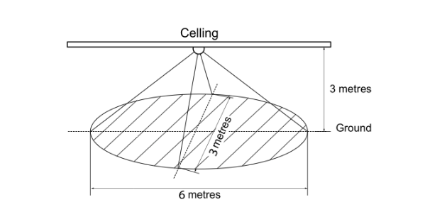
If installing MultiSensor 6 in a corner where the wall meets the ceiling it can take measurements within a 2.5 x 3.5 x 5 metres / 8 x 11 x 15 feet range: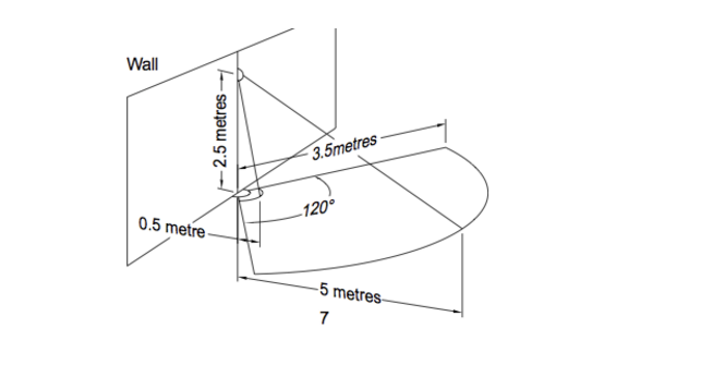
For optimal performance, your MultiSensor 6 should NOT be mounted directly on or near metal framing or other large metallic objects. Large metal objects may weaken the Z-Wave wireless signal MultiSensor 6 depends on for communication due to the wireless reflective properties of metal.
Physically install your MultiSensor.
With your MultiSensor 6 now a part of your Z-Wave network and having determined its installation location, it"s time to finish its physical installation. There are 2 ways that your MultiSensor 6 can be mounted on a wall or ceiling. Most simply it can be placed upon a shelf without the need to attach further accessories. You can mount your sensor in a corner or against a wall or ceiling by using the Back-Mount Plate. It"s also possible to embed your MultiSensor 6 within a ceiling or wall using its Recessor accessory (sold separately).
To install your MultiSensor 6:
1. You can affix the Back-Mount Arm by Double-Sided Tape or using the provided KA2.5×20 mm screws.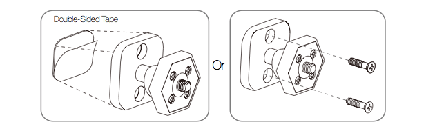
Tips: We suggest you choose the second method (using screws to affix the Back-Mount Arm) would be more stable.
2. After you have completed the affixing of Back-Mount Arm, you will need to lock the MultiSensor to the Back-Mount Arm by screwing the MultiSensor in.
3. The Back-Mount Arm may be locked at various angles by turning the Friction Lock clockwise and counter-clockwise to respectively tighten or loosen the angle of the arm. You can rotate the Friction Lock to change the measurement area of sensor.

Inclusion/Exclusion
On factory default the device does not belong to any Z-Wave network. The device needs to be added to an existing wireless network to communicate with the devices of this network. This process is called Inclusion.
Devices can also be removed from a network. This process is called Exclusion. Both processes are initiated by the primary controller of the Z-Wave network. This controller is turned into exclusion respective inclusion mode. Inclusion and Exclusion is then performed doing a special manual action right on the device.
Inclusion
Exclusion
1. Press the button on the back of the MultiSensor 6 onceProduct Usage
Advanced Functions.
Your MultiSensor has built in battery level detection. It will automatically report its battery level to the associated controller/gateway throughout its life until the battery is fully drained and needs replacing. The battery status will often be displayed in the user interface of the controller/ gateway. When used properly in an optimised Z-Wave network, your MultiSensor can be powered by batteries for 24 months before battery replacement is necessary.
Recommendation: For networks which do not offer a method to display
the battery level of your MultiSensor, it is recommended that the sensor be tested occasionally to ensure that the batteries still hold enough charge to operate. Batteries naturally lose their charge over time.
Outdoor installation.
Please note that when installed outdoors of your home, your MultiSensor should only be relied on for temperature, light, humidity, and ultraviolet readings, where as the motion sensing capabilities should be disabled on your gateway in order to avoid false motion readings. If selecting an outdoor location, it"s important to position your MultiSensor in a sheltered location. It is best if your MultiSensor is not directly exposed to rain, and is important that the humidity venting on your MultiSensor never is.
If you wish to use the Multisensor 6 outdoors, you will need to lower settings, and angle the Multisensor 6 accordingly as all environments will require different solutions or different settings for the motion sensor to work properly. Parameter 4 [1 byte] will determine the sensitivity of the motion sensor from a value range of 0 disabled to 5 max sensitivity (your ability to configure this setting will depend on the gateway used).
Testing Health Connectivity.
You can determine the health of your Multisensor 6s connectivity to your gateway using a manual button press, hold, and release function which is indicated by the LED color.
1. Press and hold the Multisensor 6 Action button
2. Wait until the RGB LED turns into a Purple Color
3. Release the Multisensor 6 Action Button
The RGB LED will blink its Purple color while sending ping messages to your gateway, when it has finished, it will blink 1 of 3 colors:
Red = Bad Health
Yellow = Moderate Health
Green = Great Health
Be sure to watch for the blink, as it will only blink once very quickly.
Node Information Frame
The Node Information Frame (NIF) is the business card of a Z-Wave device. It contains information about the device type and the technical capabilities. The inclusion and exclusion of the device is confirmed by sending out a Node Information Frame. Beside this it may be needed for certain network operations to send out a Node Information Frame. To issue a NIF execute the following action: Pressing the Z-Wave button once will trigger sending the Wake up notification command
Communication to a Sleeping device (Wakeup)
This device is battery operated and turned into deep sleep state most of the time to save battery life time. Communication with the device is limited. In order to communicate with the device, a static controller C is needed in the network. This controller will maintain a mailbox for the battery operated devices and store commands that can not be received during deep sleep state. Without such a controller, communication may become impossible and/or the battery life time is significantly decreased.
This device will wakeup regularly and announce the wakeup state by sending out a so called Wakeup Notification. The controller can then empty the mailbox. Therefore, the device needs to be configured with the desired wakeup interval and the node ID of the controller. If the device was included by a static controller this controller will usually perform all necessary configurations. The wakeup interval is a tradeoff between maximal battery life time and the desired responses of the device. To wakeup the device please perform the following action: Pressing the Z-Wave button once will trigger sending the Wake up notification command. If press and hold the Z-Wave button for 3 seconds, the MultiSensor will wake up for 10 minutes.
Quick trouble shooting
Here are a few hints for network installation if things dont work as expected.
- Make sure a device is in factory reset state before including. In doubt exclude before include.
- If inclusion still fails, check if both devices use the same frequency.
- Remove all dead devices from associations. Otherwise you will see severe delays.
- Never use sleeping battery devices without a central controller.
- Dont poll FLIRS devices.
- Make sure to have enough mains powered device to benefit from the meshing
Firmware-Update over the Air
This device is capable of receiving a new firmware 'over the air'. The update function needs to be supported by the central controller. Once the controller starts the update process, perform the following action to confirm the firmware update: Wake up the device
Association - one device controls an other device
Z-Wave devices control other Z-Wave devices. The relationship between one device controlling another device is called association. In order to control a different device, the controlling device needs to maintain a list of devices that will receive controlling commands. These lists are called association groups and they are always related to certain events (e.g. button pressed, sensor triggers, ...). In case the event happens all devices stored in the respective association group will receive the same wireless command wireless command, typically a 'Basic Set' Command.
Association Groups:
| Group Number | Maximum Nodes | Description |
|---|---|---|
| 1 | 5 | Lifeline |
Configuration Parameters
Z-Wave products are supposed to work out of the box after inclusion, however certain configuration can adapt the function better to user needs or unlock further enhanced features.
IMPORTANT: Controllers may only allow configuring signed values. In order to set values in the range 128 ... 255 the value sent in the application shall be the desired value minus 256. For example: To set a parameter to 200 it may be needed to set a value of 200 minus 256 = minus 56. In case of a two byte value the same logic applies: Values greater than 32768 may needed to be given as negative values too.
Parameter 2: Enable/Disable waking up for 10 minutes when re-power on (battery mode) the MultiSensor.
Enable/Disable waking up for 10 minutes when re-power on (battery mode) the MultiSensor. Size: 1 Byte, Default Value: 0
| Setting | Description |
|---|---|
| 0 | Disable |
| 1 | Enable. |
Parameter 3: Set the PIR time.
The default PIR time is 4 minutes. The Multisensor will send BASIC SET CC (0x00) to the associated nodes if no motion is triggered again in 4 minutes. Size: 2 Byte, Default Value: 240
| Setting | Description |
|---|---|
| 10 - 3600 | The range of PIR time is 10 to 3600. |
Parameter 4: Set the sensitivity of motion sensor.
Set the sensitivity of motion sensor. Size: 1 Byte, Default Value: 5
| Setting | Description |
|---|---|
| 0 | The current PIR sensitivity level=0.(minimum level) |
| 1 | The current PIR sensitivity level=1. |
| 2 | The current PIR sensitivity level=2. |
| 3 | The current PIR sensitivity level=3. |
| 4 | The current PIR sensitivity level=4. |
| 5 | The current PIR sensitivity level=5. (maximum level) |
Parameter 5: Which command would be sent when the motion sensor triggered.
To set which command would be sent when the motion sensor is triggered. Size: 1 Byte, Default Value: 1
| Setting | Description |
|---|---|
| 1 | Send Basic Set CC |
| 2 | Send Sensor Binary Report CC |
Parameter 8: Set the timeout of awake after the Wake Up CC is sent out..
Set the timeout of awake after the Wake Up CC is sent out.. Size: 1 Byte, Default Value: 15
| Setting | Description |
|---|---|
| 10 - 30 | Available rang is 10 to 30 seconds. |
Parameter 9: Report the current power mode and the product state for battery power mode
Report the current power mode and the product state for battery power mode.Note: this parameter cannot be used as Set usage. Size: 2 Byte, Default Value: 0
| Setting | Description |
|---|---|
| 0 | The current power mode is USB power mode. |
| 256 | The current power mode is Battery power mode. |
| 257 | The current power mode is Battery mode and the product state is awake for 10 minutes. |
Parameter 39: Configure the default low battery value.
Configure the default low battery value. When the current battery level is lower than this value, it will send out the low battery alarm. Size: 1 Byte, Default Value: 20
| Setting | Description |
|---|---|
| 10 - 50 | Available rang is 10% to 50%. |
Parameter 40: Enable/disable the selective reporting only when measurements reach a certain threshold or percentage
Enable/disable the selective reporting only when measurements reach a certain threshold or percentage. This is used to reduce network traffic. Note: If USB power, the Sensor will check the threshold every 10 seconds. If battery power, the Sensor will check the threshold when it is waken up. Size: 1 Byte, Default Value: 0
| Setting | Description |
|---|---|
| 0 | Disable |
| 1 | Enable. |
Parameter 41: Threshold change in temperature to induce an automatic report.
Threshold change in temperature to induce an automatic report.
Note: 1. The unit is Fahrenheit for US version, Celsius for EU/AU version. 2. High byte is the threshold value. Low byte is the unit (0x01=Celsius, 0x02=Fahrenheit). 3. The threshold value (high byte) contains one decimal point. E.g. if the value is set to 20 (0x001401), the threshold value = 2.0°C (EU/AU version) or if the value is set to 20 (0x001402), the threshold value= 2.0°F (US version). When the current temperature gap is more then 2.0, which will induce a temperature report to be sent out.
Size: 4 Byte, Default Value: 20
| Setting | Description |
|---|---|
| -128 - 127 | Available rang is -12.8°C to 12.7°C. |
Parameter 42: Threshold change in humidity to induce an automatic report
Threshold change in humidity to induce an automatic report.
Note: The unit is %.2. The default value is 10, which means that if the current humidity gap is more than 10%, it will send out a humidity report.
Size: 1 Byte, Default Value: 10
| Setting | Description |
|---|---|
| 1 - 100 | Available rang is 1% to 100%. |
Parameter 43: Threshold change in luminance to induce an automatic report.
Threshold change in luminance to induce an automatic report. Size: 2 Byte, Default Value: 100
| Setting | Description |
|---|---|
| 1 - 30000 | Available rang is 1LUX to 30000LUX. |
Parameter 44: Threshold change in battery level to induce an automatic report.
Threshold change in battery level to induce an automatic report.
Note: The unit is %.2. The default value is 10, which means that if the current battery level gap is more than 10%, it will send out a battery report.
Size: 1 Byte, Default Value: 10
| Setting | Description |
|---|---|
| 1 - 100 | Available rang is 1% to 100%. |
Parameter 45: Threshold change in ultraviolet to induce an automatic report.
Threshold change in ultraviolet to induce an automatic report. Size: 1 Byte, Default Value: 2
| Setting | Description |
|---|---|
| 1 - 11 | Available rang is 1 to 11. |
Parameter 46: Enable/disable to send the alarm report of low temperature
Enable/disable to send the alarm report of low temperature(<-15°C).
Note: If it is enabled, the MultiSensor will send a report of Multi Level Temperature CC to controller when the current temperature is less than -15°C).
Size: 1 Byte, Default Value: 0
| Setting | Description |
|---|---|
| 0 | Disable |
| 1 | Enable. |
Parameter 48: Enable/disable to send a report when the measurement is more than the upper limit value or less than the lower limit value.
Enable/disable to send a report when the measurement is more than the upper limit value or less than the lower limit value. Size: 1 Byte, Default Value: 0
| Setting | Description |
|---|---|
| 0 | Disable |
| 1 | Enable. |
Parameter 49: Set the upper limit value of temperature sensor.
Set the upper limit value of temperature sensor. When the measurement is more than this upper limit, which will trigger to sent out a sensor report. Size: 4 Byte, Default Value: 824
| Setting | Description |
|---|---|
| -400 - 2120 | Available rang is -40.0°F to 212.0°F (-40.0°C - 100°C) |
Parameter 50: Set the lower limit value of temperature sensor.
Set the lower limit value of temperature sensor. When the measurement is less than this lower limit, which will trigger to sent out a sensor report. High byte is the lower limit value. Size: 4 Byte, Default Value: 320
| Setting | Description |
|---|---|
| 10 - 255 | Available rang is 1.0°F to 25.5 °F (1°C- 25,5°C) |
Parameter 51: Set the upper limit value of humidity sensor.
Set the upper limit value of humidity sensor. when the measurement is more than this upper limit, which will trigger to sent out a sensor report. Size: 1 Byte, Default Value: 60
| Setting | Description |
|---|---|
| 0 - 100 | Available rang is 0% to 100%. |
Parameter 52: Set the lower limit value of humidity sensor.
Set the lower limit value of humidity sensor. When the measurement is less than this lower limit, which will trigger to sent out a sensor report. Size: 1 Byte, Default Value: 50
| Setting | Description |
|---|---|
| 0 - 100 | Available rang is 0% to 100%. |
Parameter 53: Set the upper limit value of Lighting sensor
Set the upper limit value of Lighting sensor. When the measurement is more than this upper limit, which will trigger to sent out a sensor report. Size: 1 Byte, Default Value: 1000
| Setting | Description |
|---|---|
| 0 - 30000 | Available rang is 0 to 30000LUX. |
Parameter 54: Set the lower limit value of Lighting sensor.
Set the lower limit value of Lighting sensor. When the measurement is less than this lower limit, which will trigger to sent out a sensor report. Size: 1 Byte, Default Value: 100
| Setting | Description |
|---|---|
| 0 - 30000 | Available rang is 0 to 30000LUX. |
Parameter 55: Set the upper limit value of ultraviolet sensor.
Set the upper limit value of ultraviolet sensor. When the measurement is more than this upper limit, which will trigger to sent out a sensor report. Size: 1 Byte, Default Value: 8
| Setting | Description |
|---|---|
| 1 - 11 | Available rang is 1 to 11. |
Parameter 56: Set the lower limit value of ultraviolet sensor.
Set the lower limit value of ultraviolet sensor. When the measurement is less than this upper limit, which will trigger to sent out a sensor report. Size: 1 Byte, Default Value: 4
| Setting | Description |
|---|---|
| 1 - 11 | Available rang is 1 to 11. |
Parameter 57: Set the recover limit value of temperature sensor.
Note:1. When the current measurement <= (Upper limit - Recover limit), the upper limit report is enabled and then it would send out a sensor report when the next measurement is more than the upper limit. After that the upper limit report would be disabled again until the measurement <= (Upper limit - Recover limit).2. When the current measurement >= (Lower limit + Recover limit), the lower limit report is enabled and then it would send out a sensor report when the next measurement is less than the lower limit. After that the lower limit report would be disabled again until the measurement >= (Lower limit + Recover limit).3. High byte is the recover limit value. Low byte is the unit (0x01=Celsius, 0x02=Fahrenheit). Size: 2 Byte, Default Value: 20
| Setting | Description |
|---|---|
| 10 - 255 | Available rang is 1.0°F to 25.5°F (1.0°C to 25.5°) |
Parameter 58: Set the recover limit value of humidity sensor.
Set the recover limit value of humidity sensor.Note:1. When the current measurement <= (Upper limit - Recover limit), the upper limit report is enabled and then it would send out a sensor report when the next measurement is more than the upper limit. After that the upper limit report would be disabled again until the measurement <= (Upper limit - Recover limit).2. When the current measurement >= (Lower limit + Recover limit), the lower limit report is enabled and then it would send out a sensor report when the next measurement is less than the lower limit. After that the lower limit report would be disabled again until the measurement >= (Lower limit + Recover limit). Size: 1 Byte, Default Value: 5
| Setting | Description |
|---|---|
| 1 - 50 | Available rang is 1 to 50% |
Parameter 59: Set the recover limit value of Lighting sensor.
Set the recover limit value of Lighting sensor.Note:1. When the current measurement <= (Upper limit - Recover limit), the upper limit report is enabled and then it would send out a sensor report when the next measurement is more than the upper limit. After that the upper limit report would be disabled again until the measurement <= (Upper limit - Recover limit).2. When the current measurement >= (Lower limit + Recover limit), the lower limit report is enabled and then it would send out a sensor report when the next measurement is less than the lower limit. After that the lower limit report would be disabled again until the measurement >= (Lower limit + Recover limit). Size: 1 Byte, Default Value: 100
| Setting | Description |
|---|---|
| 1 - 127 | Available rang is 10Lux to 1270Lux |
Parameter 60: Set the recover limit value of Ultraviolet sensor.
Set the recover limit value of Ultraviolet sensor.Note:1. When the current measurement <= (Upper limit - Recover limit), the upper limit report is enabled and then it would send out a sensor report when the next measurement is more than the upper limit. After that the upper limit report would be disabled again until the measurement <= (Upper limit - Recover limit).2. When the current measurement >= (Lower limit + Recover limit), the lower limit report is enabled and then it would send out a sensor report when the next measurement is less than the lower limit. After that the lower limit report would be disabled again until the measurement >= (Lower limit + Recover limit). Size: 1 Byte, Default Value: 2
| Setting | Description |
|---|---|
| 1 - 5 | Available rang is 1 to 5. |
Parameter 61: Get the out-of-limit state of the Sensors.
Get the out-of-limit state of the Sensors. Size: 2 Byte, Default Value: 0
| Setting | Description |
|---|---|
| 1 | Temperature sensor is out of the lower limit |
| 2 | Humidity sensor is out of the lower limit |
| 4 | Luminance sensor is out of the lower limit |
| 8 | Ultraviolet sensor is out of the lower limit |
| 16 | Temperature sensor is out of the upper limit |
| 32 | Humidity sensor is out of the upper limit |
| 64 | Luminance sensor is out of the upper limit |
| 128 | Ultraviolet sensor is out of the upper limit |
Parameter 64: Set the default unit of the automatic temperature report in parameter 101-103.
Set the default unit of the automatic temperature report in parameter 101-103. Size: 1 Byte, Default Value: 2
| Setting | Description |
|---|---|
| 1 | The unit is Celsius. |
| 2 | The unit is Fahrenheit. |
Parameter 100: Set the parameter 101-103 to default values.
Set the parameter 101-103 to default values. Size: 1 Byte, Default Value: 0
| Setting | Description |
|---|---|
| 1 | Set the parameter 101-103 to default values. |
Parameter 101: To set which report would be sent in Report group 1
To set which report would be sent in Report group 1.Note:You can also set all sensor reports to be sent out at the same time. E.g. If you want the batter report and temperature report to be sent out at the same time, you just need to set the configuration value to 33 (1+32). Size: 4 Byte, Default Value: 241
| Setting | Description |
|---|---|
| 1 | Battery Report is enabled. |
| 16 | Ultraviolet Report is enabled. |
| 32 | Temperature Report is enabled. |
| 64 | Humidity Report is enabled. |
| 128 | Luminance Report is enabled. |
Parameter 102: To set which report would be sent in Report group 2
To set which report would be sent in Report group 2.Note:You can also set all sensor reports to be sent out at the same time. E.g. If you want the batter report and temperature report to be sent out at the same time, you just need to set the configuration value to 33 (1+32). Size: 4 Byte, Default Value: 0
| Setting | Description |
|---|---|
| 1 | Battery Report is enabled. |
| 16 | Ultraviolet Report is enabled. |
| 32 | Temperature Report is enabled. |
| 64 | Humidity Report is enabled. |
| 128 | Luminance Report is enabled. |
Parameter 103: To set which report would be sent in Report group 3
To set which report would be sent in Report group 3.Note:You can also set all sensor reports to be sent out at the same time. E.g. If you want the batter report and temperature report to be sent out at the same time, you just need to set the configuration value to 33 (1+32). Size: 4 Byte, Default Value: 0
| Setting | Description |
|---|---|
| 1 | Battery Report is enabled. |
| 16 | Ultraviolet Report is enabled. |
| 32 | Temperature Report is enabled. |
| 64 | Humidity Report is enabled. |
| 128 | Luminance Report is enabled. |
Parameter 110: Reset Parameter 111-113
Set 111-113 to default. Size: 1 Byte, Default Value: 0
| Setting | Description |
|---|---|
| 0 | disable |
| 1 | enable |
Parameter 111: To set the interval time of sending reports in Report group 1
To set the interval time of sending reports in Report group 1 Size: 4 Byte, Default Value: 3600
| Setting | Description |
|---|---|
| 5 - 2678400 | Available rang is 5 to 2678400 seconds. |
Parameter 112: To set the interval time of sending reports in Report group 2
To set the interval time of sending reports in Report group 2 Size: 4 Byte, Default Value: 3600
| Setting | Description |
|---|---|
| 5 - 2678400 | Available rang is 5 to 2678400 seconds. |
Parameter 113: To set the interval time of sending reports in Report group 3
To set the interval time of sending reports in Report group 3 Size: 4 Byte, Default Value: 3600
| Setting | Description |
|---|---|
| 5 - 2678400 | Available rang is 5 to 2678400 seconds. |
Parameter 201: Temperature sensor calibration
Temperature sensor calibration.Note:1. High byte is the calibration value. Low byte is the unit (0x01=Celsius, 0x02=Fahrenheit)2. The calibration value (high byte) contains one decimal point. E.g. if the value is set to 20 (0x1401), the calibration value is 2.0 °C (EU/AU version) or if the value is set to 20 (0x1402), the calibration value is 2.0 °F(US version)3. The calibration value (high byte) = standard value - measure value.E.g. If measure value =25.3°C and the standard value = 23.2°C, so the calibration value= 23.2°C - 25.3°C = -2.1°C (0xEB).If the measure value =30.1°C and the standard value = 33.2°C, so the calibration value= 33.2°C - 30.1°C = 3.1°C (0x1F). Size: 2 Byte, Default Value: 0
| Setting | Description |
|---|---|
| -128 - 127 | Available rang is -12.8°C to 12.7°C. |
Parameter 202: Humidity sensor calibration
Humidity sensor calibration.The calibration value = standard value - measure value.E.g. If measure value =80RH and the standard value = 75RH, so the calibration value= 75RH - 80RH= -5RH (0xFB).If the measure value =85RH and the standard value = 90RH, so the calibration value= 90RH - 85RH=5RH (0x05). Size: 1 Byte, Default Value: 0
| Setting | Description |
|---|---|
| -50 - 50 | Available rang is -50RH to 50RH. |
Parameter 203: Luminance sensor calibration
Luminance sensor calibration.The calibration value = standard value - measure value.E.g. If measure value =800Lux and the standard value = 750Lux, so the calibration value= 750 - 800= -50 (0xFFCE).If the measure value =850Lux and the standard value = 900Lux, so the calibration value= 900 - 850=50 (0x0032) Size: 2 Byte, Default Value: 0
| Setting | Description |
|---|---|
| -1000 - 1000 | Available rang is -1000Lux to 1000Lux. |
Parameter 204: Ultraviolet sensor calibration
Ultraviolet sensor calibration.The calibration value = standard value - measure value.E.g. If measure value =9 and the standard value = 8, so the calibration value= 8 - 9= -1 (0xFE).If the measure value =7 and the standard value = 9, so the calibration value= 9 - 7=2 (0x02). Size: 1 Byte, Default Value: 0
| Setting | Description |
|---|---|
| -10 - 10 | Available rang is -10 to 10. |
Parameter 252: Enable/disable all configuration parameters to be locked
Enable/disable all configuration parameters to be locked. Size: 1 Byte, Default Value: 0
| Setting | Description |
|---|---|
| 0 | Disable |
| 1 | Enable. |
Parameter 255: Reset to factory defaults.
Reset to factory defaults. Size: 4 Byte, Default Value: 0
| Setting | Description |
|---|---|
| 1 | Reset all configuration parameters to factory defaults. |
| 1431655765 | Reset the product to factory defaults. |
Technical Data
| Dimensions | 45x45x40 mm |
| Weight | 31 gr |
| Hardware Platform | ZM5101 |
| EAN | 1220000013100 |
| Battery Type | 2 * CR123A |
| Device Type | Multilevel Sensor |
| Network Operation | Reporting Sleeping Slave |
| Z-Wave Version | 6.51.06 |
| Certification ID | ZC10-16065113 |
| Z-Wave Product Id | 0x0086.0x0002.0x0064 |
| Firmware Updatable | Updatable by Consumer by RF |
| Sensors | HumidityUltraviolet IndexLuminanceVibration/Shock (Binary)TemperatureMotion/No Motion (Binary) |
| IP (Ingress Protection) Rated | ok |
| Frequency | Europe - 868,4 Mhz |
| Maximum transmission power | 5 mW |
Supported Command Classes
- Association Group Information
- Association V2
- Basic
- Battery
- Sensor Binary
- Configuration
- Device Reset Locally
- Firmware Update Md V2
- Manufacturer Specific V2
- Notification V3
- Powerlevel
- Security
- Sensor Multilevel V5
- Version V2
- Wake Up V2
- Zwaveplus Info V2
Controlled Command Classes
- Basic
Explanation of Z-Wave specific terms
- Controller — is a Z-Wave device with capabilities to manage the network. Controllers are typically Gateways,Remote Controls or battery operated wall controllers.
- Slave — is a Z-Wave device without capabilities to manage the network. Slaves can be sensors, actuators and even remote controls.
- Primary Controller — is the central organizer of the network. It must be a controller. There can be only one primary controller in a Z-Wave network.
- Inclusion — is the process of adding new Z-Wave devices into a network.
- Exclusion — is the process of removing Z-Wave devices from the network.
- Association — is a control relationship between a controlling device and a controlled device.
- Wakeup Notification — is a special wireless message issued by a Z-Wave device to announces that is able to communicate.
- Node Information Frame — is a special wireless message issued by a Z-Wave device to announce its capabilities and functions.