Shelly
Shelly Qubino Z-Wave Wave Pro 1
SKU: ALREZWE_W_PRO1


Quickstart
This is a
Important safety information
Please read this manual carefully. Failure to follow the recommendations in this manual may be dangerous or may violate the law. The manufacturer, importer, distributor and seller shall not be liable for any loss or damage resulting from failure to comply with the instructions in this manual or any other material. Use this equipment only for its intended purpose. Follow the disposal instructions. Do not dispose of electronic equipment or batteries in a fire or near open heat sources.Product Description
The Device is a DIN rail mountable smart switch with potential-free contacts. It controls the on/off function for one electrical device with a load up to 16 A. It is compatible with switches (default) and push-buttons.
Installation
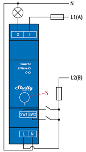
N - Neutral terminal
L - Live terminal (110–240 V AC)
SW1 - Switch/push-button input terminal (controlling O)
SW2 - Switch/push-button input terminal
I - Load circuit input terminal
O - Load circuit output terminal
Product Usage
Push-button connected to input terminal SW1
If the SW is configured as a push-button in the Device settings, each press of the push-button changes the output state O (O1) to opposite - ON, OFF, ON, etc.
1x click: Change the state of the output state O (O1) to the opposite one and send command to the associated devices in associated groups 2 and 3 (check chapter Z-Wave Association)
2x click: If the delay between first in second click is less then 500ms, this is interpreted as double clik. Send command to the associated devices (dimmers, shutters,….) in associated groups 2 and 3 (check chapter Z-Wave Association)
Hold: Send command to the associated devices in associated group 3 (check chapter Z-Wave Association)
Release: Send command to the associated devices in associated group 3 (check chapter Z-Wave Association)
Push-button connected to input terminal SW2
1x click: Toggles between on/off commands, sending a command to device groups 4 (on/off) or 5 (SSLC) (applicable to root single-channel devices only).
Hold: Sends an association command to initiate level adjustment for devices in group 5 (SSLC) (root single-channel devices only). Refer to the Z-Wave Association chapter for details.
Release: Sends an association command to cease level adjustment for devices in group 5 (SSLC) (root single-channel devices only). Refer to the Z-Wave Association chapter for details.
Supported load types
Resistive (incandescent bulbs, heating devices)
Capacitive (capacitor banks, electronic equipment, motor start capacitors)
Inductive with RC Snubber (LED light drivers, transformers, fans, refrigerators, air-conditioners)
LED Signalisation
Normal modeRemoved/Excluded: The LED will be blinking blue in Mode 1 for 10 min after every power cycle and 10 min after S button pressed.
Added/Included: The LED will be blinking green in Mode 1 for 10 min after every power cycle and 10 min after S button pressed.
Settings in progress:
Factory reset and reboot: During factory reset, the LED will turn solid green for approx. 1sec, then the blue and red LED will be blinking 0,1s On, 0,1s Off for about 2sec.
Adding / Removing: During adding or removing, the LED will be blinking blue in Mode 2.
Firmware updating OTA: During the OTA update, the LED will be blinking blue and red in Mode 2.
Checking power supply 230 V AC frequency or 24 V DC voltage: During checking the power supply, the LED will be blinking blue and red in Mode 5.
Settings mode with S button:
Adding / Removing menu selected: When the menu is selected the LED will be on blue, for maximum of 10 seconds.
Adding / Removing menu - while pressing S- button - Add/Remove process selected: When the menu is executing the LED will be blinking blue in Mode 3.
Factory reset menu selected: When the menu is selected the LED will be on red, for maximum of 10 seconds.
Factory reset - while pressing S - button - Factory reset process selected: When the menu is executing the LED will be blinking red in Mode 3.
Alarm Mode:
Overheat detected : The LED will be blinking red in Mode 4
LED blinking modes:
Mode 1 0,5s On/2s Off
Mode 2 0,5s On/0,5s Off
Mode 3 0,1s On/0,1s Off
Mode 4 (1x to 6x - 0,2s On/0,2s Off) + 2s Off
Mode 5 0,2s On blue/0,2s On red
| Reset to factory default | 1. To enter the Setting mode, quickly press and hold the S button on the Device until the LED turns solid blue. 2. Press the S button multiple times until the LED turns solid red. 3. Press and hold (> 2s) S button on the Device until the red LED starts blinking in Mode 3. Releasing the S button will start the factory reset. 4. During factory reset, the LED will turn solid green for about 1s, then the blue and red LED will start blinking in Mode 3 for approx. 2s. 5. The blue LED will be blinking in Mode 1 if the Factory reset is successful. |
| Inclusion | 1. To enter the Setting mode, quickly press and hold the S button on the Device until the LED turns solid blue. 2. Quickly release and then press and hold (> 2s) the S button on the Device until the blue LED starts blinking in Mode 3. Releasing the S button will start the Learn mode. 3. The blue LED will be blinking in Mode 2 during the adding process. 4. The green LED will be blinking in Mode 1 if the Device is successfully added to a Z-Wave® network. |
| Exclusion | 1. To enter the Setting mode, quickly press and hold the S button on the Device until the LED turns solid blue. 2. Quickly release and then press and hold (> 2s) the S button on the Device until the blue LED starts blinking in Mode 3. Releasing the S button will start the LEARN MODE. 3. The blue LED will be blinking in Mode 2 during the removing process. 4. The blue LED will be blinking in Mode 1 if the Device is successfully removed from a Z-Wave® network. |
| NIF | XXXNIF |
| Wakeup | XXXWakeupDescription |
| Protection | XXXProtection |
| FirmwareUpdate | XXXFirmwareUpdate |
| SetAssociation | XXXSetAssociation |
Association Groups:
| Group Number | Maximum Nodes | Description |
|---|---|---|
| 1 | 9 | Lifeline |
| 2 | 9 | Basic ON /OFF : It is assigned to switch connected to the SW (SW1) termina |
| 3 | 9 | Switch Multilevel: It is assigned to switch connected to the SW (SW1) terminal |
| 4 | 9 | Basic ON/OFF: It is assigned to switch connected to the SW2 terminal |
| 5 | 9 | Switch Multilevel: It is assigned to switch connected to the SW (SW2) terminal |
Configuration Parameters
Parameter 1: SW (SW1) Switch type
This parameter defines as what type the device should treat the switch connected to the SW (SW1) terminal. Size: 1 Byte, Default Value: 2
| Setting | Description |
|---|---|
| 0 | momentary switch |
| 1 | toggle switch (contact closed - ON / contact opened - OFF) |
| 2 | toggle switch (device changes status when switch changes status) |
Parameter 2: SW (SW2) Switch type
This parameter defines as what type the device should treat the switch connected to the SW (SW2) terminal. Size: 1 Byte, Default Value: 2
| Setting | Description |
|---|---|
| 0 | momentary switch |
| 1 | toggle switch (contact closed - ON / contact opened - OFF) |
| 2 | toggle switch (device changes status when switch changes status) |
Parameter 17: Restore state of O (O1) after power failure
This parameter determines if on/off status is saved and restored for load connected to O (O1) after power failure. Size: 1 Byte, Default Value: 0
| Setting | Description |
|---|---|
| 0 | Device saves last on/off status and restores it after a power failure |
| 1 | Device does not save on/off status and does not restore it after a power failure, it remains off |
Parameter 19: O (O1) Auto OFF with timer
If Load O (O1) is ON, you can schedule it to turn OFF automatically after a period of time defined in this parameter. The timer is reset to zero each time the device receives an ON command, either remotely (from the Gateway or associated device) or locally from the switch. Size: 2 Byte, Default Value: 0
| Setting | Description |
|---|---|
| 0 | Auto OFF Disabled |
| 1 - 32535 | 1 - 32535 seconds (or milliseconds – see Parameter no. 25. Auto OFF timer enabled for a given amount of seconds (or milliseconds) resolution 100ms |
Parameter 20: O (O1) Auto ON with timer
If Load O (O1) is OFF, you can schedule it to turn ON automatically after a period of time defined in this parameter. The timer is reset to zero each time the device receives an OFF command, either remotely (from the Gateway or associated device) or locally from the switch. Size: 2 Byte, Default Value: 0
| Setting | Description |
|---|---|
| 0 | Auto ON Disabled |
| 1 - 32535 | 1 - 32535 seconds (or milliseconds – see Parameter no. 25. Auto ON timer enabled for a given amount of seconds (or milliseconds) resolution 100ms |
Parameter 23: O (O1) contact type - NO/NC
Set value determines the type of Relay contact type for O (O1) output. The Relay contact type can be normally open (NO) or normally closed (NC). Size: 1 Byte, Default Value: 0
| Setting | Description |
|---|---|
| 0 | NO |
| 1 | NC |
Parameter 25: Set timer units to s or ms for O (O1)
Set Timer Units to Seconds or Milliseconds Choose if you want to set the timer in seconds or milliseconds in Parameters No. 19, 20. Size: 1 Byte, Default Value: 0
| Setting | Description |
|---|---|
| 0 | timer set in seconds |
| 1 | timer set in milliseconds |
Parameter 91: Water Alarm
This parameter determines to which alarm frames and how the device should react. The parameters consist of 4 bytes, three most significant bytes are set according to the official Z-Wave protocol specification. Size: 4 Byte, Default Value: 0
| Setting | Description |
|---|---|
| 0 | no action |
| 1 | open relay |
| 2 | close relay |
Parameter 92: Smoke Alarm
This parameter determines to which alarm frames and how the device should react. The parameters consist of 4 bytes, three most significant bytes are set according to the official Z-Wave protocol specification. Size: 4 Byte, Default Value: 0
| Setting | Description |
|---|---|
| 0 | no action |
| 1 | open relay |
| 2 | close relay |
Parameter 93: CO Alarm
This parameter determines to which alarm frames and how the device should react. The parameters consist of 4 bytes, three most significant bytes are set according to the official Z-Wave protocol specification. Size: 4 Byte, Default Value: 0
| Setting | Description |
|---|---|
| 0 | no action |
| 1 | open relay |
| 2 | close relay |
Parameter 94: Heat Alarm
This parameter determines to which alarm frames and how the device should react. The parameters consist of 4 bytes, three most significant bytes are set according to the official Z-Wave protocol specification. Size: 4 Byte, Default Value: 0
| Setting | Description |
|---|---|
| 0 | no action |
| 1 | open relay |
| 2 | close relay |
Parameter 119: Reset Parameters to default
Reset all configuration parameters to factory default settings. This is a parameter to reset only configuration parameters, after reseting parameters the Device will do power cycle, the device remain included. Size: 1 Byte, Default Value: 0
| Setting | Description |
|---|---|
| 0 | Do not reset |
| 1 | Reset parameters to default value |
Parameter 120: Factory Reset
Reset to factory default settings and removed from the z-wave network Size: 4 Byte, Default Value: 0
| Setting | Description |
|---|---|
| 0 | Don’t do Factory reset |
| 1431655765 | Do the Factory reset (hex 0x55555555) |
Technical Data
| Dimensions | 18 x 94 x 68 mm |
| Weight | 59 gr |
| Hardware Platform | ZG23 |
| EAN | 3800235269091 |
| IP Class | IP 20 |
| Voltage | 230V |
| Load | 16A |
| Device Type | Switch |
| Generic Device Class | Binary Switch |
| Firmware Version | 0a.0b |
| Z-Wave Version | 07.13 |
| Certification ID | ZC14-24010391 |
| Z-Wave Product Id | 0x0460.0x0002.0x008a |
| Frequency | Europe - 868,4 Mhz |
| Maximum transmission power | 5 mW |