Shelly
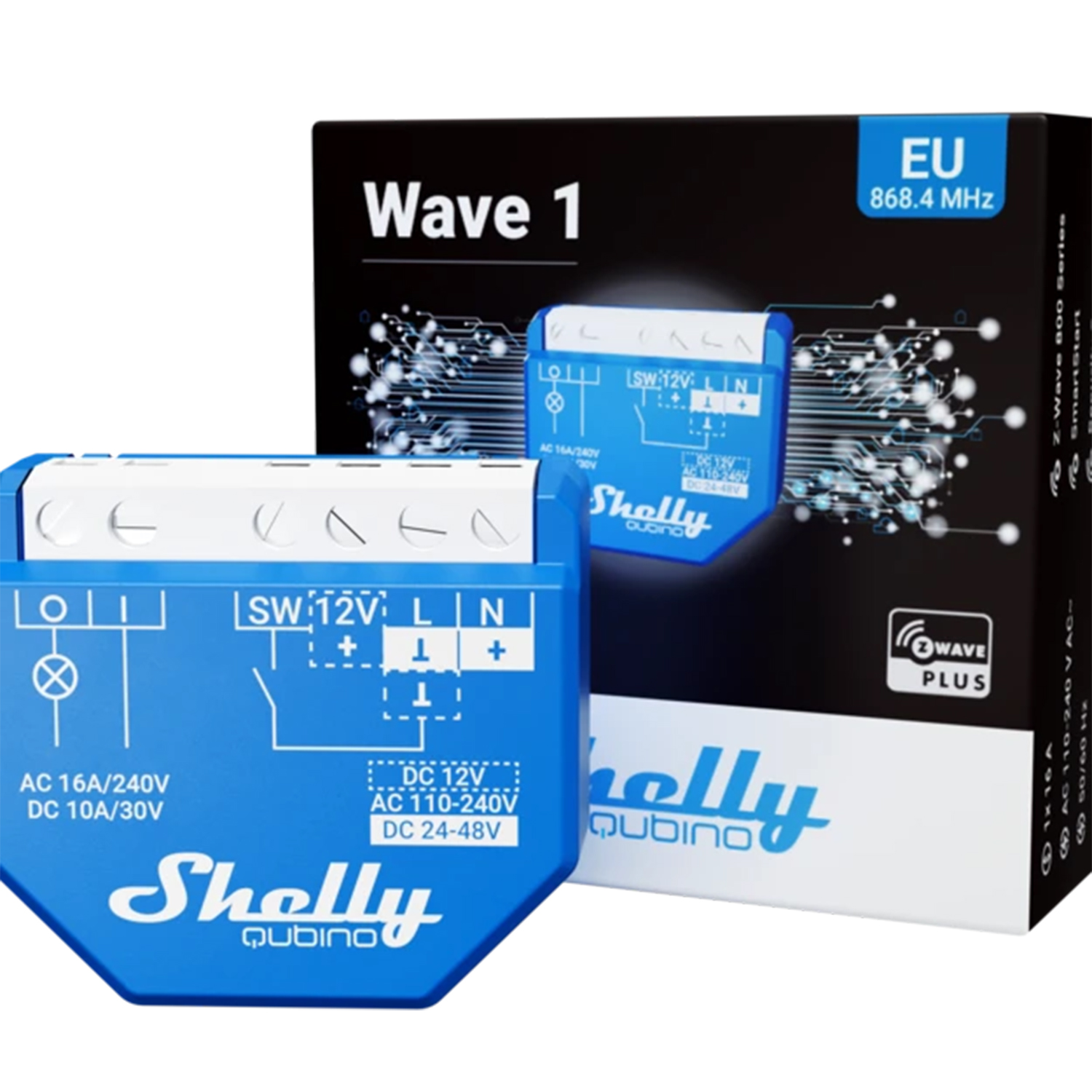
Shelly Qubino Z-Wave 1 Relay 16A
SKU: ALREZWE_W_1


Quickstart
This is a
1. With the gateway application scan the QR code on the Device label and add the Security 2 (S2) Device Specific Key (DSK) to the Provisioning List in the gateway.
2. Connect the Device to a power supply.
3. Check if the blue LED is blinking in Mode 1. If so, the Device is not added to a Z-Wave™ network.
4. Adding will be initiated automatically within a few seconds after connecting the Device to a power supply, and the Device will be added to a Z-Wave™ network automatically.
5. The blue LED will be blinking in Mode 2 during the adding process.
6. The load connected to O will be blinking 1s on/1s off/1s on/1s off if the Device is successfully added to a Z-Wave™ network.
7. The green LED will be blinking in Mode 1 if the Device is successfully added to a Z-Wave™ network.
Important safety information
Please read this manual carefully. Failure to follow the recommendations in this manual may be dangerous or may violate the law. The manufacturer, importer, distributor and seller shall not be liable for any loss or damage resulting from failure to comply with the instructions in this manual or any other material. Use this equipment only for its intended purpose. Follow the disposal instructions. Do not dispose of electronic equipment or batteries in a fire or near open heat sources.What is Z-Wave?
Z-Wave is the international wireless protocol for communication in the Smart Home. This device is suited for use in the region mentioned in the Quickstart section.
Z-Wave ensures a reliable communication by reconfirming every message (two-way communication) and every mains powered node can act as a repeater for other nodes (meshed network) in case the receiver is not in direct wireless range of the transmitter.
This device and every other certified Z-Wave device can be used together with any other certified Z-Wave device regardless of brand and origin as long as both are suited for the same frequency range.
If a device supports secure communication it will communicate with other devices secure as long as this device provides the same or a higher level of security. Otherwise it will automatically turn into a lower level of security to maintain backward compatibility.
For more information about Z-Wave technology, devices, white papers etc. please refer to www.z-wave.info.
Product Description
The Wave 1 (Device) controls on/off function for one electrical device, e.g., bulb, ceiling fan, IR heater, electrical locks, garage doors, irrigation system, etc. The output contact is potential-free (dry contact), so different power supply loads (up to 16 A) can be
connected to the Device. It is compatible with push-buttons and switches (default).
Prepare for Installation / Reset
Please read the user manual before installing the product.
In order to include (add) a Z-Wave device to a network it must be in factory default state. Please make sure to reset the device into factory default. You can do this by performing an Exclusion operation as described below in the manual. Every Z-Wave controller is able to perform this operation however it is recommended to use the primary controller of the previous network to make sure the very device is excluded properly from this network.
Reset to factory default
This device also allows to be reset without any involvement of a Z-Wave controller. This procedure should only be used when the primary controller is inoperable.
1. To enter the Setting mode, quickly press and hold the S button on the Device until the LED turns Solid blue.
2. Press the S button multiple times until the LED turns Solid red.
3. Press and hold (> 2s) S button on the Device until the red LED starts blinking in Mode 3. Releasing the S button will start the factory reset.
4. During factory reset, the LED will turn solid green for about 1s, then the blue and red LED will start blinking in Mode 3 for approx. 2s.
5. The blue LED will be blinking in Mode 1 if the Factory reset is successful.
Safety Warning for Mains Powered Devices
ATTENTION: only authorized technicians under consideration of the country-specific installation guidelines/norms may do works with mains power. Prior to the assembly of the product, the voltage network has to be switched off and ensured against re-switching.
Installation
The Device can control a various type of loads (e.g., bulbs) in one electrical circuit up to 3.5 kW / 240 V AC. It can be retrofitted into standard electrical wall boxes, behind power sockets and light switches or other places with limited space.
⚠CAUTION! Danger of electrocution. Mounting/installation of the Device to the power grid has to be performed with caution, by a qualified electrician.
⚠WARNING! Danger of electrocution. Every change in the connections has to be done after ensuring there is no voltage present at the Device terminals.
⚠CAUTION! Use the Device only with a power grid and appliances that comply with all applicable regulations. A short circuit in the power grid or any appliance connected to the Device may damage it.
⚠CAUTION! Do not connect the Device to appliances exceeding the given max. load!
⚠CAUTION! Do not shorten the antenna.
⚠RECOMMENDATION: Place the antenna as far away as possible from metal elements as they can cause signal interference.
⚠CAUTION! Connect the Device only in the way shown in these instructions. Any other method could cause damage and/or injury.
⚠CAUTION! Do not install the Device where it can get wet.
⚠CAUTION! Do not use the Device if it has been damaged!
⚠CAUTION! Do not attempt to service or repair the Device yourself!
⚠RECOMMENDATION: Connect the Device using solid single-core wires with increased insulation heat resistance not less than PVC T105°C (221°F).
⚠CAUTION! Before starting the mounting/installation of the Device, check that the breakers are turned off and there is no voltage on their terminals. This can be done with a phase tester or multimeter. When you are sure that there is no voltage, you can proceed to connecting the wires. Connect the load circuit to the Device I and O terminals.
230 V AC
If you are using AC power supply for the Device, connect the Live wire to the Device L terminal, and the Neutral wire to the N terminal . Connect a switch or a push-button to the Device SW terminal and the Live wire.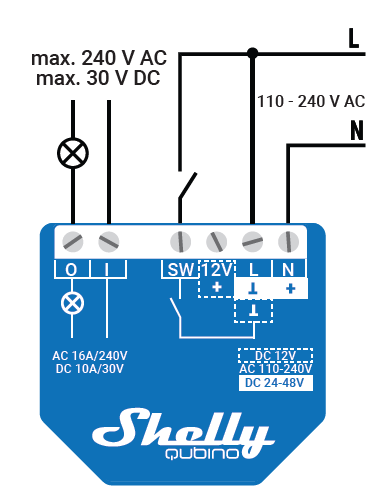
24 - 48 V DC
If you are using 24-48 V DC power supply, connect the + wire to the + and the GND wire to the terminal of the Device. 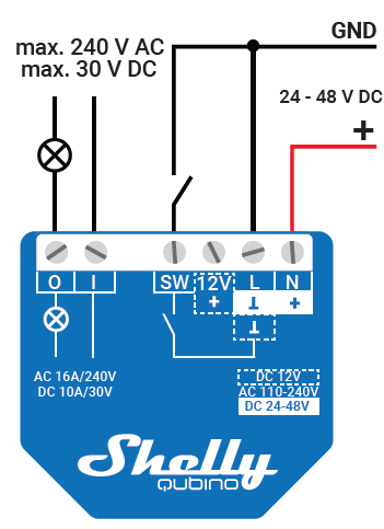
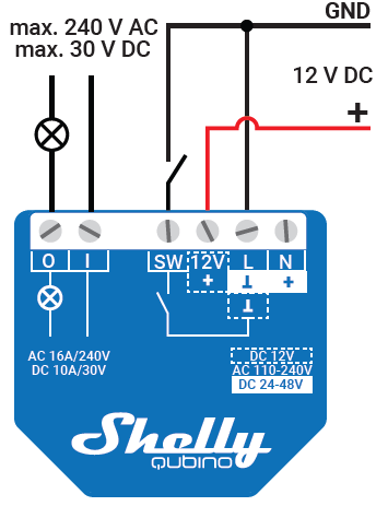
12V DC
If you are using a stabilized 12 V DC power supply, connect the + wire to the 12V+ terminal, instead to the + terminal. Connect the switch/push-button to the “SW” terminal and the GND wire.
⚠RECOMMENDATION: For inductive appliances that cause voltage spikes during switching on/off, such as electrical motors, fans, vacuum cleaners and similar ones, RC snubber (0.1 μF / 100 Ω / 1/2 W / 600 VAC) should be connected parallel to the appliance.
⚠CAUTION! Do not allow children to play with the push-buttons/switches connected to the Device. Keep the devices for remote control of Shelly Qubino (mobile phones, tablets, PCs) away from children.
LEGEND
Device terminals:
• N: Neutral terminal
• L: Live terminal (110–240 V AC)
• SW: Switch/push-button input terminal (controlling O)
• I: Load circuit input terminal
• O: Load circuit output terminal
• 12V+: 12 V DC positive terminal
• +: 24 - 48 V DC positive terminal
• Ʇ : 12 / 24 - 48 V DC ground terminal
Wires:
• N: Neutral wire
• L: Live wire (110-240 V AC)
• +: 12 / 24-48 V DC positive wire
• GND: 12 / 24-48 V DC ground wire
Inclusion/Exclusion
On factory default the device does not belong to any Z-Wave network. The device needs to be added to an existing wireless network to communicate with the devices of this network. This process is called Inclusion.
Devices can also be removed from a network. This process is called Exclusion. Both processes are initiated by the primary controller of the Z-Wave network. This controller is turned into exclusion respective inclusion mode. Inclusion and Exclusion is then performed doing a special manual action right on the device.
Inclusion
1. Connect the Device to a power supply.2. Check if the blue LED is blinking in Mode 1. If so, the Device is not added to a Z-Wave™ network.
3. Enable add/remove mode on the gateway.
4. To enter the setting mode, quickly press and hold the S button on the Device until the LED turns Solid blue.
5. Quickly release and then press and hold (> 2 s) the S button on the Device until the blue LED starts blinking in Mode 3. Releasing the S button will start the LEARN MODE.
6. The blue LED will be blinking in Mode 2 during the adding process.
7. The load connected to O will be blinking 1s on/1s off/1s on/1s off if the Device is successfully added to a Z-Wave™ network.
8. The green LED will be blinking in Mode 1 if the Device is successfully added to a Z-Wave™ network.
Exclusion
1. Connect the Device to a power supply.2. Check if the green LED is blinking in Mode 1. If so, the Device is added to a Z-Wave™ network.
3. Enable add/remove mode on the gateway.
4. To enter the Setting mode, quickly press and hold the S button on the Device until the LED turns Solid blue.
5. Quickly release and then press and hold (> 2s) the S button on the Device until the blue LED starts blinking in Mode 3. Releasing the S button will start the LEARN MODE.
6. The blue LED will be blinking in Mode 2 during the removing process.
7. The load connected to O will be blinking 1s on/1s off/1s on/1s off if the Device is successfully removed from a Z-Wave™ network.
8. The blue LED will be blinking in Mode 1 if the Device is successfully removed from a Z-Wave™ network.
Product Usage
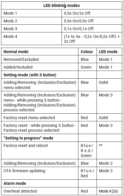
LED SIGNALIZATION
Addon interface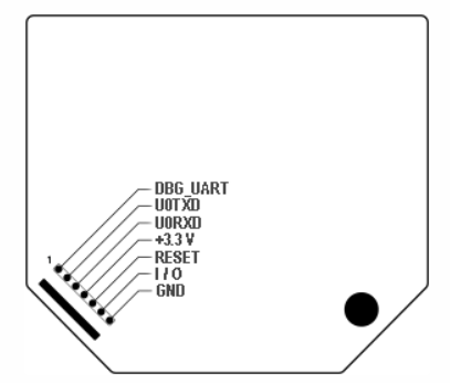
⚠CAUTION! High voltage on the add-on interface when the Device is powered!
Supported load types
- Resistive (incandescent bulbs, heating devices)
- Capacitive (capacitor banks, electronic equipment, motor start capacitors)
- Inductive with RC Snubber (LED light drivers, transformers, fans, refrigerators, air-conditioners)
Quick trouble shooting
Here are a few hints for network installation if things dont work as expected.
- Make sure a device is in factory reset state before including. In doubt exclude before include.
- If inclusion still fails, check if both devices use the same frequency.
- Remove all dead devices from associations. Otherwise you will see severe delays.
- Never use sleeping battery devices without a central controller.
- Dont poll FLIRS devices.
- Make sure to have enough mains powered device to benefit from the meshing
Association - one device controls an other device
Z-Wave devices control other Z-Wave devices. The relationship between one device controlling another device is called association. In order to control a different device, the controlling device needs to maintain a list of devices that will receive controlling commands. These lists are called association groups and they are always related to certain events (e.g. button pressed, sensor triggers, ...). In case the event happens all devices stored in the respective association group will receive the same wireless command wireless command, typically a 'Basic Set' Command.
Association Groups:
| Group Number | Maximum Nodes | Description |
|---|---|---|
| 1 | 9 | Lifeline |
| 2 | 9 | Switch 1 - Basic ON/OFF |
| 3 | 9 | Switch 1 - Multilevel |
Configuration Parameters
Z-Wave products are supposed to work out of the box after inclusion, however certain configuration can adapt the function better to user needs or unlock further enhanced features.
IMPORTANT: Controllers may only allow configuring signed values. In order to set values in the range 128 ... 255 the value sent in the application shall be the desired value minus 256. For example: To set a parameter to 200 it may be needed to set a value of 200 minus 256 = minus 56. In case of a two byte value the same logic applies: Values greater than 32768 may needed to be given as negative values too.
Parameter 1: SW (SW1) Switch type
This parameter defines as what type the device should treat the switch connected to the SW (SW1) terminal. Size: 1 Byte, Default Value: 2
| Setting | Description |
|---|---|
| 0 | momentary switch |
| 1 | toggle switch (contact closed - ON / contact opened - OFF) |
| 2 | toggle switch (device changes status when switch changes status) |
Parameter 17: Restore state of O (O1) after power failure
This parameter determines if on/off status is saved and restored for load connected to O (O1) after power failure. Size: 1 Byte, Default Value: 0
| Setting | Description |
|---|---|
| 0 | Device saves last on/off status and restores it after a power failure |
| 1 | Device does not save on/off status and does not restore it after a power failure, it remains off |
Parameter 19: O (O1) Auto OFF with timer
If Load O (O1) is ON, you can schedule it to turn OFF automatically after a period of time defined in this parameter. The timer is reset to zero each time the device receives an ON command, either remotely (from the Gateway or associated device) or locally from the switch. Size: 2 Byte, Default Value: 0
| Setting | Description |
|---|---|
| 0 | Auto OFF Disabled |
| 1 - 32535 | 1 - 32535 seconds (or milliseconds – see Parameter no. 25. Auto OFF timer enabled for a given amount of seconds (or milliseconds) resolution 100ms |
Parameter 20: O (O1) Auto ON with timer
If Load O (O1) is OFF, you can schedule it to turn ON automatically after a period of time defined in this parameter. The timer is reset to zero each time the device receives an OFF command, either remotely (from the Gateway or associated device) or locally from the switch. Size: 2 Byte, Default Value: 0
| Setting | Description |
|---|---|
| 0 | Auto ON Disabled |
| 1 - 32535 | 1 - 32535 seconds (or milliseconds – see Parameter no. 25. Auto ON timer enabled for a given amount of seconds (or milliseconds) resolution 100ms |
Parameter 23: O (O1) contact type - NO/NC
Set value determines the type of Relay contact type for O (O1) output. The Relay contact type can be normally open (NO) or normally closed (NC). Size: 1 Byte, Default Value: 0
| Setting | Description |
|---|---|
| 0 | NO |
| 1 | NC |
Parameter 25: Set timer units to s or ms for O (O1)
Set Timer Units to Seconds or Milliseconds Choose if you want to set the timer in seconds or milliseconds in Parameters No. 19, 20. Size: 1 Byte, Default Value: 0
| Setting | Description |
|---|---|
| 0 | timer set in seconds |
| 1 | timer set in milliseconds |
Parameter 91: Water Alarm
This parameter determines to which alarm frames and how the device should react. The parameters consist of 4 bytes, three most significant bytes are set according to the official Z-Wave protocol specification. Size: 4 Byte, Default Value: 0
| Setting | Description |
|---|---|
| 0 | no action |
| 1 | open relay |
| 2 | close relay |
Parameter 92: Smoke Alarm
This parameter determines to which alarm frames and how the device should react. The parameters consist of 4 bytes, three most significant bytes are set according to the official Z-Wave protocol specification. Size: 4 Byte, Default Value: 0
| Setting | Description |
|---|---|
| 0 | no action |
| 1 | open relay |
| 2 | close relay |
Parameter 93: CO Alarm
This parameter determines to which alarm frames and how the device should react. The parameters consist of 4 bytes, three most significant bytes are set according to the official Z-Wave protocol specification. Size: 4 Byte, Default Value: 0
| Setting | Description |
|---|---|
| 0 | no action |
| 1 | open relay |
| 2 | close relay |
Parameter 94: Heat Alarm
This parameter determines to which alarm frames and how the device should react. The parameters consist of 4 bytes, three most significant bytes are set according to the official Z-Wave protocol specification. Size: 4 Byte, Default Value: 0
| Setting | Description |
|---|---|
| 0 | no action |
| 1 | open relay |
| 2 | close relay |
Parameter 119: Reset Parameters to default
Reset all configuration parameters to factory default settings. This is a parameter to reset only configuration parameters, after reseting parameters the Device will do power cycle, the device remain included. Size: 1 Byte, Default Value: 0
| Setting | Description |
|---|---|
| 0 | Do not reset |
| 1 | Reset parameters to default value |
Parameter 120: Factory Reset
Reset to factory default settings and removed from the z-wave network Size: 4 Byte, Default Value: 0
| Setting | Description |
|---|---|
| 0 | Don’t do Factory reset |
| 1431655765 | Do the Factory reset (hex 0x55555555) |
Technical Data
| Dimensions | 42 x 37 x 16 mm |
| Weight | 26 gr |
| Hardware Platform | EFR32ZG23 |
| EAN | 3800235269039 |
| IP Class | IP 20 |
| Voltage | 230V |
| Load | 16 A |
| Device Type | On/Off Power Switch |
| Generic Device Class | Binary Switch |
| Firmware Version | 10.13 |
| Z-Wave Version | 07.13 |
| Certification ID | ZC14-23090326 |
| Z-Wave Product Id | 0x0460.0x0002.0x0083 |
| Frequency | Europe - 868,4 Mhz |
| Maximum transmission power | 5 mW |
Supported Command Classes
- Ss Basic
- Switch Binary
- Transport Service
- Association Grp Info
- Device Reset Locally
- Zwaveplus Info
- Supervision
- Configuration
- Alarm
- Manufacturer Specific
- Powerlevel
- Firmware Update Md
- Association
- Version
- Indicator
- Multi Channel Association
- Security
- Security 2
Explanation of Z-Wave specific terms
- Controller — is a Z-Wave device with capabilities to manage the network. Controllers are typically Gateways,Remote Controls or battery operated wall controllers.
- Slave — is a Z-Wave device without capabilities to manage the network. Slaves can be sensors, actuators and even remote controls.
- Primary Controller — is the central organizer of the network. It must be a controller. There can be only one primary controller in a Z-Wave network.
- Inclusion — is the process of adding new Z-Wave devices into a network.
- Exclusion — is the process of removing Z-Wave devices from the network.
- Association — is a control relationship between a controlling device and a controlled device.
- Wakeup Notification — is a special wireless message issued by a Z-Wave device to announces that is able to communicate.
- Node Information Frame — is a special wireless message issued by a Z-Wave device to announce its capabilities and functions.