Fibaro
FIBARO Double Smart Module
SKU: FIBEFGS-224


Quickstart
This is a
Important safety information
Please read this manual carefully. Failure to follow the recommendations in this manual may be dangerous or may violate the law. The manufacturer, importer, distributor and seller shall not be liable for any loss or damage resulting from failure to comply with the instructions in this manual or any other material. Use this equipment only for its intended purpose. Follow the disposal instructions. Do not dispose of electronic equipment or batteries in a fire or near open heat sources.Product Description
With the FIBARO Double Smart Module, you can integrate existing electrical installations (e.g. lighting, airing systems?) into a Z-Wave network. Thus, the connected devices can still be controlled with the existing wall switch, but thanks to Z-Wave also via remote control, smartphone or sensor-controlled automation.
The compact radio module is placed in a wall box right behind the normal switch. The switch is no longer directly connected to the loads but acts as input device for the FIBARO insert that is controlling the loads. The switch only sends control signal to the insert which controls the loads then again. The solution works with all switch design. You can use a momentary or a toggle switch. Its recommended to use wall boxes with 65mm depth. But smaller boxes with only 45mm depth can be used also if there is enough space behind the switch. The available space depends on the size of the traditional switch, the dimensions of the wall box and the amount of additional cabling placed in this box.
The integrated energy consumption measurement function provides how much energy the connected device use. So you can identify the energy eater in your Smart Home.
Installation
1. Switch off the mains voltage (disable the fuse) or disable the power supply.
2. Connect with one of the diagrams below:
3. Verify the correctness of connection.
4. Tighten the terminal screws using PH1 screwdriver.
5. If the device fully assembled, switch on the mains voltage or enable the power supply.
6. The LED light means the device is powered.
7. Add the device to the Z-Wave network (see the next chapter).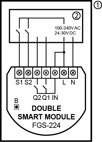
Diagram 1: Example connection of Smart Module
Notes for diagrams:
S1 -terminal for 1st button
S2 - terminal for 2nd button
Q1 - output terminal of the 1st channel
Q2 - output terminal of the 2nd channel
IN - input terminal for both channels
L - terminal for live wire
N - terminal for neutral wire
B - maintenance button
1 - device/system housing
2 - electrical device
Product Usage
Z-Wave range test
The device has a built in Z-Wave network main controllers range tester.
Note: To make Z-Wave range test possible, the device must be added to the Z-Wave controller. Testing may stress the network, so it is recommended to perform the test only in special cases.
To test the main controllers range:
- Press and hold the maintenance button to enter the menu.
- Release button when the device glows magenta.
- Quickly click the button to confirm.
- Visual indicator will indicate the Z-Wave networks range (range signaling modes described below).
- To exit Z-Wave range test, press the button briefly.
Z-Wave range tester signaling modes:
- Visual indicator pulsing green - the device attempts to establish direct communication with the main controller. If a direct communication attempt fails, the device will try to establish a routed communication, through other modules, which will be signaled by visual indicator pulsing yellow.
- Visual indicator glowing green - the device communicates with the main controller directly.
- Visual indicator pulsing yellow - the device tries to establish a routed communication with the main controller through other modules (repeaters).
- Visual indicator glowing yellow - the device communicates with the main controller through the other modules. After 2 seconds the device will retry to establish direct communication with the main controller, which will be signaled with visual indicator pulsing green.
- Visual indicator pulsing violet - the device does communicate at the maximum distance of the Z-Wave network. If the connection proves successful it will be confirmed with a yellow glow. Its not recommended to use the device at the range limit.
- Visual indicator glowing red - the device is not able to connect to the main controller directly or through another Z-Wave network device (repeater).
Visual indications
The built-in LED light shows the current device status.
After powering the device:
- Green - device added to a Z-Wave network (non-secure, S0, S2 non-authenticated),
- Magenta - device added to a Z-Wave network (Security S2 Authenticated),
- Red - device not added to a Z-Wave network.
Update:
- Blinking cyan - update in progress,
- Green - update successful,
- Red - update not successful.
Menu:
- Blinking green - entering the menu (added as non-secure, S0, S2 non-authenticated),
- Blinking magenta - entering the menu (added as Security S2 Authenticated),
- Blinking red - entering the menu (not added to a Z-Wave network),
- Magenta - test Z-Wave network range,
- Yellow - reset to factory defaults.
Menu
Menu allows them to perform Z-Wave network actions. In order to use the menu:
- Press and hold the maintenance button to enter the menu.
- LED will signal to add status for 3 seconds (see Visual indications), then turn off for another 3 seconds.
- Release the button when device signals desired position with color:
- MAGENTA - test Z-Wave network range
- YELLOW - reset to factory defaults
- Quickly click the button to confirm.
Central Szene
Switch connected to S1 terminal - Scene ID 1
Switch clicked once - Key Pressed 1 time
Switch clicked twice - Key Pressed 2 times
Switch clicked thrice* Key Pressed 3 times
Switch held** - Key Held Down
Switch released** - Key Released
Switch connected to S2 terminal - Scene ID 2
Switch clicked once - Key Pressed 1 time
Switch clicked twice - Key Pressed 2 times
Switch clicked thrice - Key Pressed 3 times
Switch held** - Key Held Down
Switch released** - Key Released
* Activating triple clicks will disallow removing using this input.
** Not available for toggle switches.
| Reset to factory default |
|
| Inclusion | Quickly, three times click button connected to S1/S2 or the maintenance button. |
| Exclusion | Quickly, three times click button connected to S1/S2 or the maintenance button. |
| NIF | XXXNIF |
| Wakeup | XXXWakeupDescription |
| Protection | XXXProtection |
| FirmwareUpdate | XXXFirmwareUpdate |
| SetAssociation | XXXSetAssociation |
Association Groups:
| Group Number | Maximum Nodes | Description |
|---|---|---|
| 1 | 1 | Lifeline |
| 2 | 5 | Basic Set Input S1 |
| 3 | 5 | Basic Set Input S2 |
Configuration Parameters
Parameter 1: Remember relays state
This parameter determines the state of relays after power supply failure (e.g. power outage). For auto OFF and flashing modes the parameter is not relevant and the relay will always remain switched off. Size: 1 Byte, Default Value: 1
| Setting | Description |
|---|---|
| 0 | Relays remain switched off after restoring power |
| 1 | Restore remembered state of relays after restoring power |
| 2 | Restore remembered state of relays after restoring power, but for toggle switches (parameter 20/21 set to 1) set the same state as the current state of the switches |
Parameter 20: S1 input - switch type
This parameter defines as what type the device should treat the switch connected to the S1 terminal. Size: 1 Byte, Default Value: 0
| Setting | Description |
|---|---|
| 0 | Momentary switch |
| 1 | Toggle switch synchronized (contact closed - ON, contact opened - OFF) |
| 2 | Toggle switch with memory (device changes status when switch changes status) |
Parameter 21: S2 input - switch type
This parameter defines as what type the device should treat the switch connected to the S2 terminal. Size: 1 Byte, Default Value: 0
| Setting | Description |
|---|---|
| 0 | Momentary switch |
| 1 | Toggle switch synchronized (contact closed - ON, contact opened - OFF) |
| 2 | Toggle switch with memory (device changes status when switch changes status) |
Parameter 24: Inputs orientation
This parameter allows reversing operation of S1 and S2 inputs without changing the wiring. Use in case of incorrect wiring. Size: 1 Byte, Default Value: 0
| Setting | Description |
|---|---|
| 0 | Default (S1 - 1st channel, S2 - 2nd channel) |
| 1 | Reversed (S1 - 2nd channel, S2 - 1st channel) |
Parameter 25: Outputs orientation
This parameter allows reversing operation of Q1 and Q2 outputs without changing the wiring. Use in case of incorrect wiring. Size: 1 Byte, Default Value: 0
| Setting | Description |
|---|---|
| 0 | Default (Q1 - 1st channel, Q2 - 2nd channel) |
| 1 | Reversed (Q1 - 2nd channel, Q2 - 1st channel) |
Parameter 30: Alarm configuration - 1st slot
This parameter determines to which alarm frames and how the device should react. The parameters consist of 4 bytes, three most significant bytes are set according to the official Z-Wave protocol specification. For a setting of this parameter, please refer to the manufacturers manual. Size: 4 Byte, Default Value: 0
| Setting | Description |
|---|
Parameter 31: Alarm configuration - 2nd slot (Water)
This parameter determines to which alarm frames and how the device should react. The parameters consist of 4 bytes, three most significant bytes are set according to the official Z-Wave protocol specification. For a setting of this parameter, please refer to the manufacturers manual. Size: 4 Byte, Default Value:
| Setting | Description |
|---|
Parameter 32: Alarm configuration - 3rd slot (Smoke)
This parameter determines to which alarm frames and how the device should react. The parameters consist of 4 bytes, three most significant bytes are set according to the official Z-Wave protocol specification. For a setting of this parameter, please refer to the manufacturers manual. Size: 4 Byte, Default Value:
| Setting | Description |
|---|
Parameter 33: Alarm configuration - 4th slot (CO)
This parameter determines to which alarm frames and how the device should react. The parameters consist of 4 bytes, three most significant bytes are set according to the official Z-Wave protocol specification.For a setting of this parameter, please refer to the manufacturers manual. For a setting of this parameter, please refer to the manufacturers manual. Size: 4 Byte, Default Value:
| Setting | Description |
|---|
Parameter 34: Alarm configuration - 5th slot (Heat)
This parameter determines to which alarm frames and how the device should react. The parameters consist of 4 bytes, three most significant bytes are set according to the official Z-Wave protocol specification. For a setting of this parameter, please refer to the manufacturers manual. Size: 4 Byte, Default Value:
| Setting | Description |
|---|
Parameter : Alarm configuration - duration
This parameter defines duration of alarm sequence. When time set in this parameter elapses, alarm is cancelled and relays restore normal operation, but do not recover state from before the alarm. Size: Byte, Default Value:
| Setting | Description |
|---|---|
| 0 | Infinite |
| 1 - 32400 | Seconds |
Parameter 40: S1 switch - scenes sent
This parameter determines which actions result in sending scene IDs assigned to them. Size: 1 Byte, Default Value: 0
| Setting | Description |
|---|---|
| 1 | Key pressed 1 time |
| 2 | Key pressed 2 times |
| 4 | Key pressed 3 times |
| 8 | Key hold down and key released |
| 15 | All |
Parameter 41: S2 switch - scenes sent
This parameter determines which actions result in sending scene IDs assigned to them. Size: 1 Byte, Default Value: 0
| Setting | Description |
|---|---|
| 1 | Key pressed 1 time |
| 2 | Key pressed 2 times |
| 4 | Key pressed 3 times |
| 8 | Key hold down and key released |
| 15 | All |
Parameter 150: First channel - operating mode
This parameter allows to choose operating mode for channel controlled with Q1 output. For timed modes (value 1, 2 or 3), time is set with parameter 154 and reaction to input change is set with parameter 152. Size: 1 Byte, Default Value: 0
| Setting | Description |
|---|---|
| 0 | Standard operation |
| 1 | Delayed OFF |
| 2 | Auto OFF |
| 3 | Flashing |
Parameter 151: Second channel - operating mode
This parameter allows to choose operating mode for channel controlled with Q2 output. For timed modes (value 1, 2 or 3), time is set with parameter 155 and reaction to input change is set with parameter 153. Size: 1 Byte, Default Value: 0
| Setting | Description |
|---|---|
| 0 | Standard operation |
| 1 | Delayed OFF |
| 2 | Auto OFF |
| 3 | Flashing |
Parameter 152: First channel - reaction to input change in delayed/auto OFF modes
This parameter determines how the device reacts when changing state of S1 input in timed modes for first channel. Size: 1 Byte, Default Value: 0
| Setting | Description |
|---|---|
| 0 | Cancel mode and set default state |
| 1 | No reaction, mode runs until it ends |
| 2 | Reset timer, start counting time from the beginning |
Parameter 153: Second channel - reaction to input change in delayed/auto OFF modes
This parameter determines how the device reacts when changing state of S2 input in timed modes for first channel. Size: 1 Byte, Default Value: 0
| Setting | Description |
|---|---|
| 0 | Cancel mode and set default state |
| 1 | No reaction, mode runs until it ends |
| 2 | Reset timer, start counting time from the beginning |
Parameter 154: First channel - time parameter for delayed/auto OFF and flashing modes
This parameter allows to set time parameter used in timed modes for first channel. For delayed/auto OFF modes it determines duration, for flashing mode it determines cycle period. Size: 2 Byte, Default Value: 5
| Setting | Description |
|---|---|
| 0 | 0-0,1 seconds |
| 1 - 32000 | 0,1 - 3200 seconds |
Parameter 155: Second channel - time parameter for delayed/auto OFF and flashing modes
This parameter allows to set time parameter used in timed modes for second channel. For delayed/auto OFF modes it determines duration, for flashing mode it determines cycle period. Size: 2 Byte, Default Value: 5
| Setting | Description |
|---|---|
| 0 | 0-0,1 seconds |
| 1 - 32000 | 0,1 - 3200 seconds |
Parameter 156: S1 input - Switch ON value sent to 2nd association group
This parameter defines value sent with Switch ON command to devices in 2nd association group when using S1 input. Size: 2 Byte, Default Value: 255
| Setting | Description |
|---|---|
| 0 | Turn off |
| 1 - 99 | Turn on and set level |
| 255 | Turn on with last level |
Parameter 157: S1 input - Switch OFF value sent to 2nd association group
This parameter defines value sent with Switch OFF command to devices in 2nd association group when using S1 input. Size: 2 Byte, Default Value: 0
| Setting | Description |
|---|---|
| 0 | Turn off |
| 1 - 99 | Turn on and set level |
| 255 | Turn on with last level |
Parameter 158: S1 input - Double Click value sent to 2nd association group
This parameter defines value sent with Double Click command to devices in 2nd association group when using S1 input. Size: 2 Byte, Default Value: 99
| Setting | Description |
|---|---|
| 0 | Turn off |
| 1 - 99 | Turn on and set level |
| 255 | Turn on with last level |
Parameter 159: S2 input - Switch ON value sent to 2nd association group
This parameter defines value sent with Switch ON command to devices in 2nd association group when using S2 input. Size: 2 Byte, Default Value: 255
| Setting | Description |
|---|---|
| 0 | Turn off |
| 1 - 99 | Turn on and set level |
| 255 | Turn on with last level |
Parameter 160: S2 input - Switch OFF value sent to 2nd association group
This parameter defines value sent with Switch OFF command to devices in 2nd association group when using S2 input. Size: 2 Byte, Default Value: 0
| Setting | Description |
|---|---|
| 0 | Turn off |
| 1 - 99 | Turn on and set level |
| 255 | Turn on with last level |
Parameter 161: S2 input - Double Click value sent to 2nd association group
This parameter defines value sent with Double Click command to devices in 2nd association group when using S2 input. Size: 2 Byte, Default Value: 99
| Setting | Description |
|---|---|
| 0 | Turn off |
| 1 - 99 | Turn on and set level |
| 255 | Turn on with last level |
Parameter 162: Q1 output type
This parameter determines type of Q1 output. Size: 1 Byte, Default Value: 0
| Setting | Description |
|---|---|
| 0 | Normally Open (relay contacts opened turned off, closed when turned on) |
| 1 | Normally Closed (relay contacts closed turned off, opened when turned on) |
Parameter 163: Q2 output type
This parameter determines type of Q2output. Size: 1 Byte, Default Value: 0
| Setting | Description |
|---|---|
| 0 | Normally Open (relay contacts opened turned off, closed when turned on) |
| 1 | Normally Closed (relay contacts closed turned off, opened when turned on) |
Parameter 164: Lock simultaneous switching of Q1 and Q2 outputs
When the lock is enabled, both outputs cannot be turned on at the same time. Size: 1 Byte, Default Value: 0
| Setting | Description |
|---|---|
| 0 | lock disabled |
| 1 | lock enabled |
Technical Data
| Dimensions | 38,25 x 20,30 x 42,50 mm |
| Weight | 29 gr |
| Hardware Platform | ZM5101 |
| EAN | 5902701702090 |
| IP Class | IP 20 |
| Voltage | 230V |
| Load | 6A |
| Device Type | Powered device |
| Generic Device Class | Binary Switch |
| Specific Device Class | Binary Power Switch |
| Firmware Version | 05.00 |
| Z-Wave Version | 06.04 |
| Certification ID | ZC10-20096968 |
| Z-Wave Product Id | 0x010f.0x0204.0x1000 |
| Frequency | Europe - 868,4 Mhz |
| Maximum transmission power | 5 mW |