Fibaro Group
Door/ Window Sensor with Temperature Sensor Option
SKU: FIB_FGK-101

Quickstart
This is a
For Inclusion and Exclusion, sending out a NIF or wakeup the device push down the tamper switch (push the device on a table) if the device is not yet mounted. Then hit the little button (B) inside of the enclosure one time.
Important safety information
Please read this manual carefully. Failure to follow the recommendations in this manual may be dangerous or may violate the law. The manufacturer, importer, distributor and seller shall not be liable for any loss or damage resulting from failure to comply with the instructions in this manual or any other material. Use this equipment only for its intended purpose. Follow the disposal instructions. Do not dispose of electronic equipment or batteries in a fire or near open heat sources.What is Z-Wave?
Z-Wave is the international wireless protocol for communication in the Smart Home. This device is suited for use in the region mentioned in the Quickstart section.
Z-Wave ensures a reliable communication by reconfirming every message (two-way communication) and every mains powered node can act as a repeater for other nodes (meshed network) in case the receiver is not in direct wireless range of the transmitter.
This device and every other certified Z-Wave device can be used together with any other certified Z-Wave device regardless of brand and origin as long as both are suited for the same frequency range.
If a device supports secure communication it will communicate with other devices secure as long as this device provides the same or a higher level of security. Otherwise it will automatically turn into a lower level of security to maintain backward compatibility.
For more information about Z-Wave technology, devices, white papers etc. please refer to www.z-wave.info.
Product Description
The Fibaro Door / Window Sensor is a battery powered, Z-Wave compatible reed sensor. It combines the functionality of 3 devices (reed, binary and temperature sensor) in one easy to use product. The sensor can be used for monitoring whether a door, window, window blind or a garage gate is open or closed. In addition, you can integrate any binary output sensor with the Z-Wave network using this sensor, e.g. motion sensors, flood sensors, alarm system sensors, etc.
The product consists of two elements. One of the parts is mounted on the moving part of the window or of the door. The other part is placed on the frame. The device needs to be included into a Z-Wave network by a remote control or any other Z-Wave controller. If an action is detected, the sensor sends a signal to the Z-Wave network main controller.
Prepare for Installation / Reset
Please read the user manual before installing the product.
In order to include (add) a Z-Wave device to a network it must be in factory default state. Please make sure to reset the device into factory default. You can do this by performing an Exclusion operation as described below in the manual. Every Z-Wave controller is able to perform this operation however it is recommended to use the primary controller of the previous network to make sure the very device is excluded properly from this network.
Safety Warning for Batteries
The product contains batteries. Please remove the batteries when the device is not used. Do not mix batteries of different charging level or different brands.
Installation
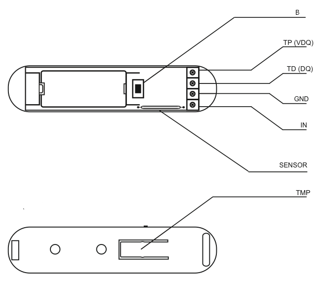
The sensor consists of two parts: The sensor main device plus a little magent that is triggering the sensor when closed to the main device. One part of the sensor is mounted on the fixed part of the door or window while the other part is mounted on the moving part in a way, that both devices are adjacent to each other with no more than 5 mm distance between them. The main device can be mounted with double sided tape however for security applications it is strongly recommended to use screws. The holes to screw the device are placed behind the battery. Hence the battery need to be removed for this procedure. The image shows the two buttons "TMP" and "B", the reed sensor and the contact terminal for external switches and sensors.

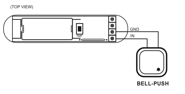
The external temperature sensor DS18B20 is connected to the device as shown in this picture. In case the sensor shall only act as temperature sensor it can be placed everywhere and there is no need to place the magnet nearby. Beside to act as temperature sensor the device can also work as simple digial sensor transmitting the status of an externally connected on/off switch. The subsequent image shows how to connect such an external switch to the pins "IN" and "GND".
Inclusion/Exclusion
On factory default the device does not belong to any Z-Wave network. The device needs to be added to an existing wireless network to communicate with the devices of this network. This process is called Inclusion.
Devices can also be removed from a network. This process is called Exclusion. Both processes are initiated by the primary controller of the Z-Wave network. This controller is turned into exclusion respective inclusion mode. Inclusion and Exclusion is then performed doing a special manual action right on the device.
Inclusion
For Inclusion and Exclusion push down the tamper switch (push the device on a table) if the device is not yet mounted. Then hit the little button (B) inside of the enclosure one time.
Exclusion
For Inclusion and Exclusion push down the tamper switch (push the device on a table) if the device is not yet mounted. Then hit the little button (B) inside of the enclosure one time.
Product Usage
The sensor reports status changes and - if a external temperature sensor is attached - the temperature using wireless Z-Wave commands. There is no further local interaction needed or possible.
Node Information Frame
The Node Information Frame (NIF) is the business card of a Z-Wave device. It contains information about the device type and the technical capabilities. The inclusion and exclusion of the device is confirmed by sending out a Node Information Frame. Beside this it may be needed for certain network operations to send out a Node Information Frame. To issue a NIF execute the following action:
For sending out a node information frame push down the tamper switch (push the device on a table) if the device is not yet mounted.Then hit the little button (B) inside of the enclosure one time.
Communication to a Sleeping device (Wakeup)
This device is battery operated and turned into deep sleep state most of the time to save battery life time. Communication with the device is limited. In order to communicate with the device, a static controller C is needed in the network. This controller will maintain a mailbox for the battery operated devices and store commands that can not be received during deep sleep state. Without such a controller, communication may become impossible and/or the battery life time is significantly decreased.
This device will wakeup regularly and announce the wakeup state by sending out a so called Wakeup Notification. The controller can then empty the mailbox. Therefore, the device needs to be configured with the desired wakeup interval and the node ID of the controller. If the device was included by a static controller this controller will usually perform all necessary configurations. The wakeup interval is a tradeoff between maximal battery life time and the desired responses of the device. To wakeup the device please perform the following action:
To wake up the device push down the tamper switch (push the device on a table) if the device is not yet mounted. Then hit the little button (B) inside of the enclosure one time.
Quick trouble shooting
Here are a few hints for network installation if things dont work as expected.
- Make sure a device is in factory reset state before including. In doubt exclude before include.
- If inclusion still fails, check if both devices use the same frequency.
- Remove all dead devices from associations. Otherwise you will see severe delays.
- Never use sleeping battery devices without a central controller.
- Dont poll FLIRS devices.
- Make sure to have enough mains powered device to benefit from the meshing
Association - one device controls an other device
Z-Wave devices control other Z-Wave devices. The relationship between one device controlling another device is called association. In order to control a different device, the controlling device needs to maintain a list of devices that will receive controlling commands. These lists are called association groups and they are always related to certain events (e.g. button pressed, sensor triggers, ...). In case the event happens all devices stored in the respective association group will receive the same wireless command wireless command, typically a 'Basic Set' Command.
Association Groups:
| Group Number | Maximum Nodes | Description |
|---|---|---|
| 1 | 5 | Group I is assigned to input IN1 (and the magnetic sensor). Sending BASIC SET or ALARM command frames. |
| 2 | 5 | Group II is assigned to TMP button. Once the button is released, ALARM GENERIC frame is sent to associated devices. |
| 3 | 1 | Group III reports on the condition of the device, only one device may be assigned to the group (main controller, by default). |
Configuration Parameters
Z-Wave products are supposed to work out of the box after inclusion, however certain configuration can adapt the function better to user needs or unlock further enhanced features.
IMPORTANT: Controllers may only allow configuring signed values. In order to set values in the range 128 ... 255 the value sent in the application shall be the desired value minus 256. For example: To set a parameter to 200 it may be needed to set a value of 200 minus 256 = minus 56. In case of a two byte value the same logic applies: Values greater than 32768 may needed to be given as negative values too.
Parameter 1: Input IN alarm cancellation delay
Additional delay after an alarm from input IN has ceased. The parameter allows user to specify additional time, after which the input IN alarm is cancelled once its violation has ceased. Size: 2 Byte, Default Value: 0000
| Setting | Description |
|---|
Parameter 2: Status change signalled by LED
Size: 1 Byte, Default Value: 00
| Setting | Description |
|---|---|
| 00 | LED turned Off |
| 01 | LED turned On |
Parameter 3: Type of IN input
Size: 1 Byte, Default Value: 00
| Setting | Description |
|---|---|
| 00 | Normal Close |
| 01 | Normal Open |
| 02 | Mono Stable |
| 03 | bistable |
Parameter 5: Type of control frame transmitted for association group 1, activated via IN input
The parameter allows you to specify the type of an alarm frame or to force control frames transmission (BASIC_SET) Size: 1 Byte, Default Value: ff
| Setting | Description |
|---|---|
| 00 | ALARM GENERIC frame |
| 01 | ALARM SMOKE frame |
| 02 | ALARM CO frame |
| 03 | ALARM CO2 frame |
| 04 | ALARM HEAT frame |
| 05 | ALARM WATER frame |
| ff | Control frame BASIC_SET |
Parameter 7: Value of the parameter specifying the forced level of dimming/opening roller blinds when u201cswitch onu201d/u201dopenu201d commands are sent to devices from association group no.1
In case of alarm frames an alarm priority is specified. Value of 255 makes it possible to activate a device. In case of the Dimmer module it means activating the device and setting it to the previously stored condition, e.g. when Dimmer is set to 30%, deactivated and then reactivated using 255 commend, it will be automatically set to the previous condition i.e. 30%. Size: 1 Byte, Default Value: ff
| Setting | Description |
|---|---|
| 01 - 63 | Dimming level |
| ff | Turn On |
Parameter 9: Deactivating transmission of the alarm cancelling frame or the control frame deactivating the device (Basic)
It allows for disabling the function of deactivating the device and cancelling alarms for devices associated with IN input. Size: 1 Byte, Default Value: 00
| Setting | Description |
|---|---|
| 00 | for association group no. 1 information is sent |
| 01 | for association group no. 1 information is not sent |
Parameter 12: Sensitivity to temperature changes
The maximum acceptable difference between the last reported temperature and the current temperature read from the sensor. If the temperatures differ by the set value or more, a report with the current temperature value is sent to the device assigned to association group no. 3. To set an appropriate parameter value use the following formula: x = delta T x 16 - for Celsius; x = delta T x 80 / 9 - for Fahrenheit; x = parameter value; delta T - maximum acceptable temperature gradient in Celsius or Fahrenheit. If the value is set to 0: - if the wake-up interval is set to 255 seconds, temperature report will be sent according to the interval; - if the wake-up interval is set to over 255, temperature report will be sent each ca. 4 minutes. Available parameter settings: 0 - 255 [0oC to 16oC] [32oF - 60,8oF] Size: 1 Byte, Default Value: 08
| Setting | Description |
|---|
Parameter 13: Sending an alarm or control frame (for IN input, depending on parameter no.5 value), and TMP button alarm frame
The frame is sent in u201cbroadcastu201d mode, i.e. to all devices within range - information sent in this mode is not repeated by the mesh network. Size: 1 Byte, Default Value: 00
| Setting | Description |
|---|---|
| 00 | IN and TMP Broadcast mode inactive |
| 01 | IN broadcast mode active, TMP broadcast mode inactive |
| 02 | IN broadcast mode inactive, TMP broadcast mode active |
| 03 | IN and TMP broadcast mode active |
Parameter 14: Scene activation functionality
IN input: Switch from u201coffu201d to u201conu201d ID10; Switch from u201conu201d to u201coffu201d ID11; Remaining IDs are recognized correctly if the value of parameter no.3 was set to 2 Holding down ID12; Releasing ID13; Double click ID14; Triple click ID 15; Scene activation functionality may shorten the battery life, even by 25%. Size: 1 Byte, Default Value: 00
| Setting | Description |
|---|---|
| 00 | functionality deactivated |
| 01 | functionality activated |
Technical Data
| Dimensions | 0.0180000x0.0750000x0.0190000 mm |
| Weight | 10 gr |
| Hardware Platform | ZM3102 |
| EAN | 5902020528111 |
| Battery Type | 1 * CR2 |
| Device Type | Routing Binary Sensor |
| Generic Device Class | Binary Sensor |
| Specific Device Class | Routing Binary Sensor |
| Firmware Version | 02.01 |
| Z-Wave Version | 03.2a |
| Certification ID | ZC08-14060004 |
| Z-Wave Product Id | 010f.0700.1000 |
| Frequency | Europe - 868,4 Mhz |
| Maximum transmission power | 5 mW |
Supported Command Classes
- Multi Channel
- Basic
- Wake Up
- Association
- Version
- Sensor Binary
- Battery
- Configuration
- Manufacturer Specific
- Firmware Update Md
- Sensor Alarm
Explanation of Z-Wave specific terms
- Controller — is a Z-Wave device with capabilities to manage the network. Controllers are typically Gateways,Remote Controls or battery operated wall controllers.
- Slave — is a Z-Wave device without capabilities to manage the network. Slaves can be sensors, actuators and even remote controls.
- Primary Controller — is the central organizer of the network. It must be a controller. There can be only one primary controller in a Z-Wave network.
- Inclusion — is the process of adding new Z-Wave devices into a network.
- Exclusion — is the process of removing Z-Wave devices from the network.
- Association — is a control relationship between a controlling device and a controlled device.
- Wakeup Notification — is a special wireless message issued by a Z-Wave device to announces that is able to communicate.
- Node Information Frame — is a special wireless message issued by a Z-Wave device to announce its capabilities and functions.